2 Phase Stepper Driver—MC542
MC542 is a new generation of digital 2-phase hybrid stepping motor drive based on a DSP with advanced control algorithm. Arbitrary microstepping within 128 and any current value within the rated current can be set according to users’ needs.Due to it increases the function of automatic identification of motor parameters inside, corresponding operation parameters can be set for different motors, which make motors run smoothly, noise very low.
It’s suitable for all kinds of automation equipment and instruments in the field of motion control ,such as: electronic processing and detection, semiconductor packaging, laser cutting and welding, laser typesetting, packing machines, engraving machine, marking machine, cutting machine, apparel plotter, NC machine tools, automated assembly equipment, etc. It’s the first choice for users that prefer low noise, high speed with superior performance and with a stronger price competition.
| drive function | operating instructions |
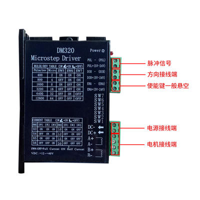
| Working current setting | The driver output current is set by 3 dip switches SW1 - SW3, its output current has 8 floors in all. About specific output current Settings, please refer to the drive panel. |
| Automatic half flow function | Users can set drive to automatic half flow function through SW4.OFF shows the static current is set to be half of the dynamic current, ON shows the static current is the same as dynamic current .SW4 should be set to OFF in general use in order to reduce the heating of the motor and driver , also to improve the reliability. The current will reduce by 50% automatically 0.3 seconds approximately after the pulse train stop (55% actual value), calorific value reduced by 65% in theory. |
| Micro step subdivision setting | The driver micro step subdivision is set by 4 dip switches SW5 -SW8, there are 15 files of micro step subdivisions in all.When users are setting segmentation, the driver should be stopped first. About the setting of micro step subdivision , please refer to the drive panel. |
| Indicator light | Drives have two red and green lights.One of the green light is power light, It will be abidingly on after the driver is electrified; the other red light is fault indicating lamp, when being overvoltage and overcurrent problems,trouble light will be abidingly on. After the fault being cleared, the red light turns off. When a driver becomes disabled, only re-up electricity and reuse can clear the fault. |
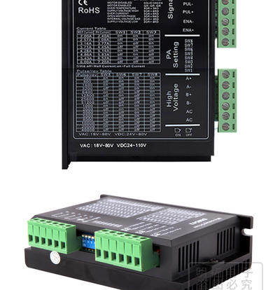
| Signal interface | PUL + and PUL - are the plus side and minus side of signal controlling.DIR + and DIR - are the plus side and minus side of direction signal.ENA + and ENA -are the plus side and minus side of enable signal. |
| Motor interface | A + and A - connectting the plus and minus side of step motor A phase winding. B + B and B -connectting the plus and minus side of step motor B phase winding. When A, B two phase winding exchanges, can make the motor to reverse direction. |
| Power port | Using the dc power to supply, operating voltage range is suggested to be 24V-50VDC. Power is greater than 100 w. |
| Installation instructions | The boundary dimension of drive is : 117 * 78 * 34 mm,the Installation pitch-row is 111 mm. Either horizontal or vertical installation can work,(vertical installation is recommended).When installation, should make it close to the metal cabinet to facilitate heat dissipation. |
MC542 driver uses eight dip switches to set the segmentation accuracy, dynamic current and half/full flow, detailed description as below:


Contact
Supplier