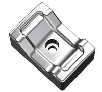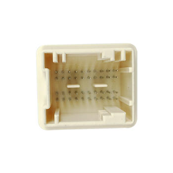

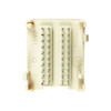
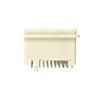
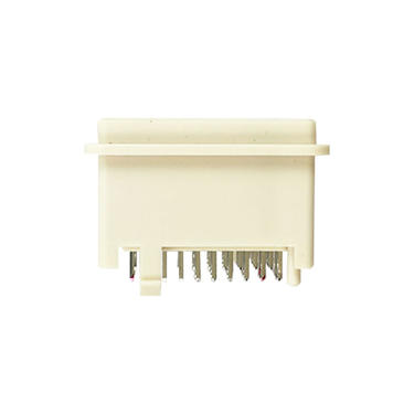

Electronic connector product by precision injection molding
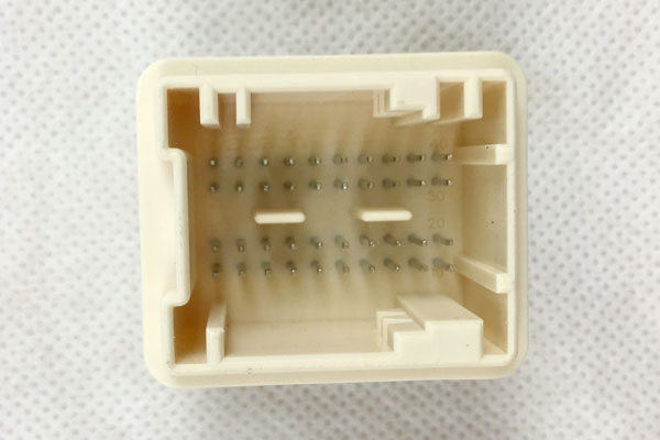
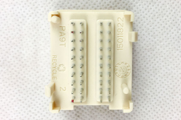
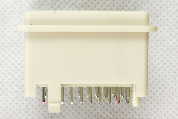
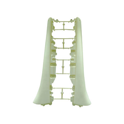
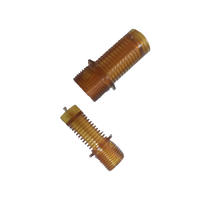
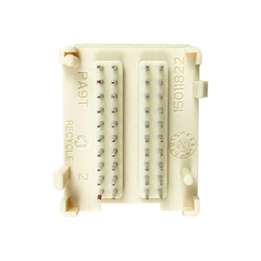
This part is simple,but need to ensure 40pcs pin locate properly when plastic filling,specially under high pressure flow.To save production cost,we need to cut down cycle time.So two or three even more over-mold inserts need.Injection machine operator no need to set pin one by one into mold.Just need to set in additional insert before molding.When mold open,just need put whole insert with pin into core.Of course,operator need to take part with insert together.The hooks on both sides are undercut,need design for slider or angle lifter.But no slider split line allow in middle surface.So split line should be set on radius of corner.
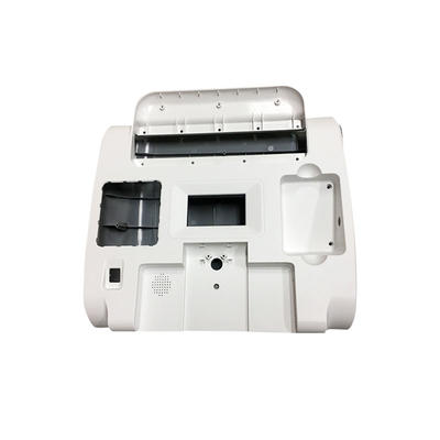
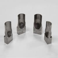
The molded part is ejected via knockout pins.In addition to providing for ejection.these pins serve to vent the cavity during filling.It is in part for this reason that the knockout pins are located beneath ribs and other deep section of the part.where entrapped air is to be expected.The mold filling pattern during injection of the molding compound as well as the mechanical and thermal aspects of the mold design were simulated and established during the design phase with the aid of appropriate computer programs.
Contact
Supplier