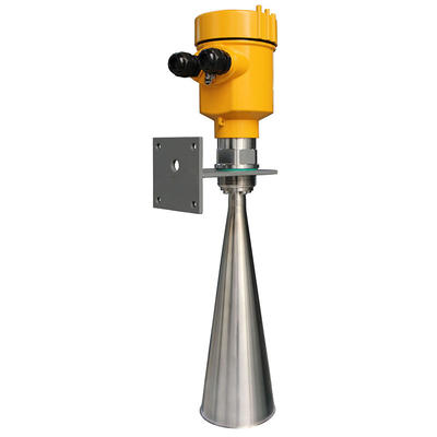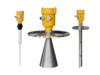
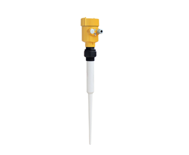
Kaidi KD-R80X High precision level meter High Frequency digital Radar Level Transmitter
Application:
6GHz radar level gauge is suitable for liquid, paste, granule and block material level and non-contact measurement, suitable for changes in temperature, pressure big; there is an inert gas and volatile.
The measurement method of microwave pulse, can work normally in the industrial frequency band range. The beam energy is low, can be installed on all kinds of metal, non-metallic container or pipe, no harm to human body and environment.
| Suitable for Medium: | Liquid, especially for corrosive liquid |
| Explosion-proof Grade: | Exia IIC T6 Ga/ Exd IIC T6 Gb |
| Measuring Range: | 20m |
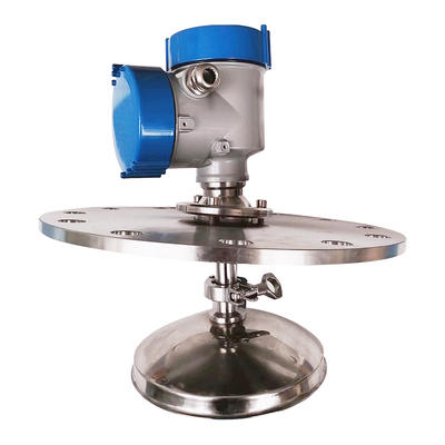
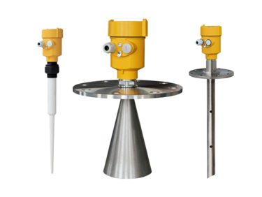
| Aerials: | The Rod Antenna (PTFE) |
| Frequency: | 6 GHz |
| Temperature: | -40℃~130℃ |
| Measurement Precision: | ±10mm |
| Process Pressure: | (-0.1 ~ 1.6) Mpa |
| The signal Output: | (4 ~ 20) mA/HART |
| The Scene Display: | Four LCD /Can be programmed |
| Power Source: | Two-wire (DC24V) 、Four-wire (DC24V/AC220V) |
| Repeatability: | ± 1mm |
| Outer Covering : | Aluminum /Plastic /Stainless steel |
| Connection: | With PTFE plate flange |


1. Dimensions of Instruments
l The rod antenna radar size (unit: mm)

l
The rod antenna radar size (unit: mm)

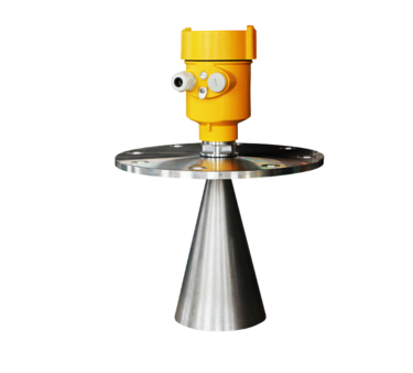
l Horn antenna size (unit: mm)

l Horn size (unit: mm)

l Flange Selection (unit: mm)

2. The Electrical Connection
l The power supply voltage:
| (4~20)mA/HART (Two wire system) | The power supply and the output current signal sharing a two core shield cable. The supply voltage range see technical data. For intrinsically safe type must be a safety barrier between the power supply and the instrument. |
| (4~20)mA/HART(Four wire system) | Separate power supply and the current signal, respectively using a two-core shielded cable. The supply voltage range see technical data. |
| RS485 / Modbus | Power supply and Modbus signal line are separated, respectively using a two-core shielded cable, the power supply voltage range see technical data. |
l Connection mode:
Ø
24V two wire wiring diagram as follows:

Ø
220V four wire connection is as below:

Ø 24V RS485/Modbus wiring diagram as follows:

l Explosion Proof Connection
The intrinsic safety version sensors (Exia IIc T6) use Alu-die casting housing and filling Silicone rubber sealants internal structure aimed to prevent sparks resulted from circuit failure from leaking out. It is applicable for the continuous level measurement of flammable medium under Exia IIc T6.
A safety barrier FBS-2 must be used together with the intrinsic safety instrument. It is an associated device to this product for the power supply of this product. The main specification is intrinsic safety: Exia IIC, voltage of power supply: 24V DC±5%, short-circuit current: 135mA, operating current: 4...20mA.
All cables must be shielded. The max length is 500m for the cable from the barrier to the sensor. Stray capacitor≤0.1μF/Km, stray inductance 1mH/Km. Instrument must be connected to the ground potential. Any unapproved associated device is not allowed to be used.

l Protection grade:
This instrument meets the protection class IP66/67 requirements, please ensure the waterproof cable sealing head. The following diagram:

3. Programming and Debugging
l There are three kinds of debugging method:
1) Display / Keyboard
2) Host debugging
3) HART handheld programmer
l Display / Keyboard:
Please debug the instrumentation by four buttons on the display screen. There are three debug menu languages optional. After debugging is generally used only for display, through the glass window can read measured value very clearly.
l Display / Keyboard

l PC debugging:
Connected to PC by HART

l HART handheld programmer:

4. Technical Parameters
| General data | |
| Materials | |
| Antenna | PTFE, PP |
| Outer Covering | Aluminum, Plastic, Anti-static PP, Stainless steel 316 |
| The seal housing and the housing | Silicone Rubber |
| Shell window | Polycarbonate |
| Ground terminal | Stainless steel |
| Process connection | |
| 801 | G1½″A Thread & 1½″NPT Thread / Flange (optional) |
| 802 | With PTFE plate flange |
| 803 | Stainless Steel Flanges |
| 804 | Stainless Steel Flanges |
| 805 | Stainless Steel Flanges |
| 806 | Stainless Steel Flanges |
| Supply voltage | |
| Two-wire | |
| Standard | (16~26)V DC |
| Intrinsically Safe | (21.6~26.4)V DC |
| Power Consumption | Max.22.5mA |
| Allowable ripple | |
| <100HzH47 | Uss < lV |
| - (100~100K)Hz | Uss < l0mV |
| Flameproof | |
| (22.8 ~ 26.4) V DC 2-wire system | |
| (198 ~242)V AC 4-wire system / 110V AC 4-wire system | |
| Power Consumption Max. 1VA,1W | |
| Cable parameters | |
| Cable entry / plug | 1 M20xl.5 cable entry (cable diameter 5 ~ 9mm) |
| 1 blind blocking M20xl.5 | |
| Spring terminals | For wire cross-section 2.5mm² |
| Output parameters | |
| The output signal | (4~20)mA / HART |
| Resolution | 1.6μA |
| Fault signal | Current output unchanged;20.5mA;22mA;3.9mA |
| Two-wire load resistor | See below |
| Four-wire resistive load | The maximum 500Ω |
| Integration time | (0 ~ 36) s, adjustable |


Contact
Supplier