Features
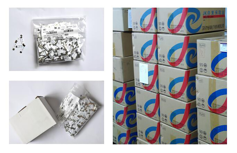
◇ Strap devices,Axial leaded
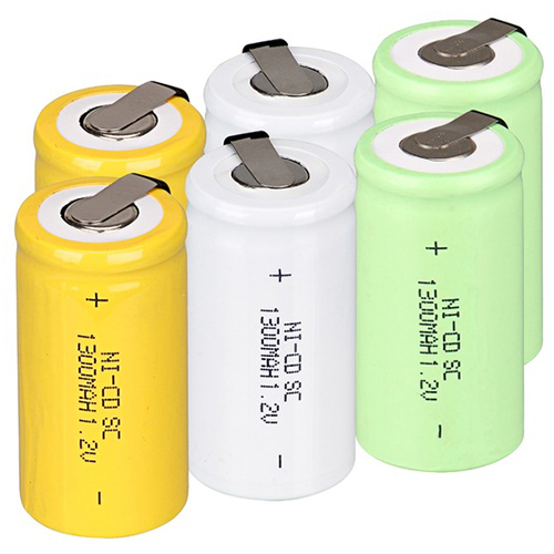
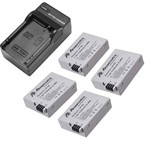
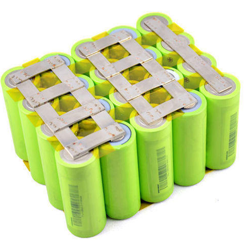
◆ Protection for NiCd/NiMH rechargesble battery packs,Li-ion/Polymer Li-ion battery
◇ Lead-free
◆ Halogen free
◇ Agency recognition:UL、CSA、TUV


◇ Strap devices,Axial leaded
◆ Protection for NiCd/NiMH rechargesble battery packs,Li-ion/Polymer Li-ion battery
◇ Lead-free
◆ Halogen free
◇ Agency recognition:UL、CSA、TUV
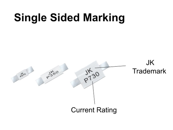
❈ Product Video
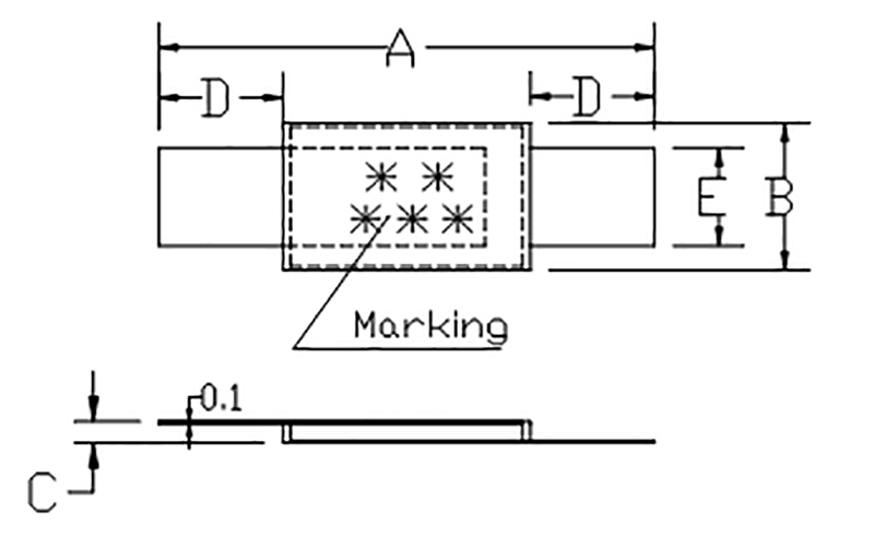
Model | A | B | C | D | E | |||||
Min | Max | Min | Max | Min | Max | Min | Max | Min | Max | |
JK-P070 | 17.0 | 22.1 | 4.9 | 5.5 | 0.4 | 1.0 | 3.5 | 6.0 | 3.8 | 4.2 |
JK-P100 | 17.0 | 22.1 | 4.9 | 5.5 | 0.4 | 1.0 | 3.5 | 6.0 | 3.8 | 4.2 |
JK-P120 | 17.0 | 22.1 | 4.9 | 5.5 | 0.4 | 1.0 | 3.5 | 6.0 | 3.8 | 4.2 |
JK-P175 | 20.9 | 23.1 | 4.6 | 5.5 | 0.4 | 1.0 | 3.5 | 6.0 | 3.8 | 4.2 |
JK-P180 | 20.9 | 23.1 | 4.6 | 5.5 | 0.4 | 1.0 | 3.5 | 6.0 | 3.8 | 4.2 |
JK-P190 | 20.9 | 23.1 | 4.6 | 5.5 | 0.4 | 1.0 | 3.5 | 6.0 | 3.8 | 4.2 |
JK-P200 | 20.9 | 23.1 | 4.6 | 5.5 | 0.4 | 1.0 | 3.5 | 6.0 | 3.8 | 4.2 |
JK-P210 | 20.9 | 23.1 | 4.6 | 5.5 | 0.4 | 1.0 | 3.5 | 6.0 | 3.8 | 4.2 |
JK-P260 | 20.9 | 23.1 | 4.6 | 5.5 | 0.4 | 1.0 | 3.5 | 6.0 | 3.8 | 4.2 |
JK-P300 | 24.0 | 27.5 | 6.9 | 7.5 | 0.4 | 1.0 | 4.0 | 7.5 | 4.8 | 5.2 |
JK-P350 | 24.0 | 27.5 | 6.9 | 7.5 | 0.4 | 1.0 | 4.0 | 7.5 | 4.8 | 5.2 |
JK-P380 | 24.0 | 27.5 | 6.9 | 7.5 | 0.4 | 1.0 | 4.0 | 7.5 | 4.8 | 5.2 |
JK-P420 | 24.0 | 27.5 | 9.8 | 10.5 | 0.4 | 1.0 | 4.0 | 7.5 | 4.8 | 5.2 |
JK-P450 | 24.0 | 27.5 | 9.8 | 10.5 | 0.4 | 1.0 | 4.0 | 7.5 | 4.8 | 5.2 |
JK-P550 | 24.0 | 27.5 | 9.8 | 10.5 | 0.4 | 1.0 | 4.0 | 7.5 | 4.8 | 5.2 |
JK-P600 | 27.1 | 29.1 | 13.9 | 14.5 | 0.4 | 1.0 | 4.1 | 5.5 | 5.9 | 6.6 |
JK-P730 | 27.1 | 29.1 | 13.9 | 14.5 | 0.4 | 1.0 | 4.1 | 5.5 | 5.9 | 6.6 |
JK-P900 | 45.4 | 47.6 | 7.9 | 8.5 | 0.4 | 1.0 | 4.6 | 6.2 | 5.9 | 6.1 |
JK-P1410 | 58.0 | 60.0 | 13.4 | 14.0 | 0.4 | 1.0 | 4.2 | 5.8 | 5.9 | 6.1 |
Thermal Derating Chart-IH(A)
JK-P Series
Model | Maximum ambient operating temperatures(℃) | |||||||||
-40 | -20 | 0 | 25 | 40 | 50 | 60 | 70 | 80 | 85 | |
JK-P070 | 1.1 | 1.0 | 0.8 | 0.7 | 0.5 | 0.4 | 0.3 | 0.2 | 0.2 | 0.1 |
JK-P100 | 1.8 | 1.6 | 1.4 | 1.0 | 0.8 | 0.7 | 0.6 | 0.4 | 0.3 | 0.2 |
JK-P120 | 1.9 | 1.7 | 1.5 | 1.2 | 1.0 | 0.9 | 0.8 | 0. 6 | 0.5 | 0.4 |
JK-P175 | 2.5 | 2.2 | 2.0 | 1.75 | 1.4 | 1.3 | 1.2 | 1.0 | 0.9 | 0.8 |
JK-P180 | 2.6 | 2.3 | 2.1 | 1.8 | 1.4 | 1.3 | 1.2 | 1.0 | 0.9 | 0.8 |
JK-P190 | 2.8 | 2.5 | 2.3 | 1.9 | 1.5 | 1.4 | 1.3 | 1.1 | 0.9 | 0.8 |
JK-P200 | 3.1 | 2.8 | 2.5 | 2.0 | 1. 7 | 1.5 | 1.4 | 1.2 | 1.0 | 0.9 |
JK-P210 | 3.3 | 3.0 | 2.7 | 2.1 | 1.8 | 1.6 | 1.5 | 1.3 | 1.1 | 1.0 |
JK-P260 | 3.8 | 3.4 | 3.1 | 2.6 | 2.2 | 2.0 | 1.9 | 1.7 | 1.4 | 1.3 |
JK-P300 | 5.1 | 4.4 | 3.7 | 3.0 | 2.3 | 1.9 | 1.6 | 1.2 | 0.9 | 0.7 |
JK-P350 | 5.3 | 4.8 | 4.3 | 3.5 | 3.0 | 2.7 | 2.5 | 2.1 | 1.8 | 1.7 |
JK-P380 | 5.4 | 4.9 | 4.4 | 3.8 | 3.3 | 3.0 | 2.8 | 2.5 | 2.3 | 2.1 |
JK-P420 | 6.3 | 5.7 | 5.1 | 4.2 | 3.6 | 3.3 | 3.0 | 2.6 | 2.2 | 2.1 |
JK-P450 | 6.5 | 5.8 | 5.3 | 4.5 | 3.9 | 3.6 | 3.3 | 2.9 | 2.6 | 2.4 |
JK-P550 | 7.6 | 6.9 | 6.2 | 5..5 | 4.7 | 4.3 | 4.0 | 3.6 | 3.2 | 3.0 |
JK-P600 | 8.7 | 7.8 | 7.1 | 6.0 | 5.2 | 4.7 | 4.4 | 3.9 | 3.4 | 3.2 |
JK-P730 | 10.5 | 9.5 | 8.6 | 7.3 | 6.3 | 5.7 | 5.4 | 4.7 | 4.2 | 4.0 |
JK-P900 | 12.7 | 11.4 | 10 | 9.0 | 7.5 | 6.8 | 6.2 | 5.5 | 4.9 | 4.5 |
JK-P1410 | 19.9 | 17.8 | 15.7 | 14.1 | 11.8 | 10.8 | 9.7 | 8.7 | 7.7 | 7.2 |
Electrical Characteristic
Ihold=Hold current: maximum current device will not trip in 25℃ still air.
Itrip= Trip current: minimum current device will always trip in 25℃ still air.
Vmax=Maximum voltage device can withstand without damage at rated current(Imax).
Imax=Maximum fault current device can withstand without damage at rated voltage(vmax).
Pd max= Typical power dissipation: typical amount of power dissipated by the device when in state air environment.
Maximum Time-to-trip=Maximum time to trip(s) at assigned current.
Rmin=Minimum device resistance prior to tripping at 25℃.
Rmax=Maximum device resistance prior to tripping at 25℃.
R1max=Maximum device resistance one hour after it is tripped at 25℃
Model | Ihold | Itrip | Vmax | Imax | Pd | Maximum Time-to-trip | Rmin | Rmax | R1max | |
(A) | (A) | (V) | (A) | (W) | Current(A) | Time(S) | (Ω) | (Ω) | (Ω) | |
JK-P070 | 0.70 | 1.45 | 16 | 100 | 1.60 | 3.5 | 5.0 | 100 | 200 | 400 |
JK-P100 | 1.00 | 2.50 | 16 | 100 | 1.60 | 5.0 | 5.0 | 70 | 130 | 260 |
JK-P120 | 1.20 | 2.70 | 16 | 100 | 1.60 | 6.0 | 5.0 | 60 | 120 | 240 |
JK-P175 | 1.75 | 3.80 | 16 | 100 | 1.60 | 8.5 | 5.0 | 30 | 65 | 130 |
JK-P180 | 1.80 | 3.80 | 16 | 100 | 1.60 | 9.0 | 5.0 | 30 | 60 | 120 |
JK-P190 | 1.90 | 4.20 | 16 | 100 | 1.60 | 9.5 | 5.0 | 25 | 45 | 90 |
JK-P200 | 2.00 | 4.40 | 16 | 100 | 1.60 | 10.0 | 5.0 | 20 | 40 | 80 |
JK-P210 | 2.10 | 4.40 | 16 | 100 | 1.60 | 10.5 | 5.0 | 20 | 35 | 70 |
JK-P260 | 2.60 | 5.20 | 16 | 100 | 1.60 | 13.0 | 5.0 | 15 | 30 | 60 |
JK-P300 | 3.00 | 6.30 | 24 | 100 | 2.40 | 15.0 | 5.0 | 15 | 31 | 62 |
JK-P350 | 3.50 | 7.00 | 24 | 100 | 2.40 | 17.5 | 5.0 | 17 | 31 | 62 |
JK-P380 | 3.80 | 7.60 | 24 | 100 | 2.40 | 19.0 | 5.0 | 13 | 22 | 44 |
JK-P420 | 4.20 | 8.30 | 24 | 100 | 2.00 | 21.0 | 5.0 | 12 | 24 | 48 |
JK-P450 | 4.50 | 9.00 | 20 | 100 | 2.00 | 22.5 | 5.0 | 11 | 20 | 40 |
JK-P550 | 5.50 | 10.50 | 20 | 100 | 2.00 | 27.5 | 5.0 | 9 | 16 | 32 |
JK-P600 | 6.00 | 11.70 | 20 | 100 | 2.80 | 30.0 | 5.0 | 7 | 14 | 28 |
JK-P730 | 7.30 | 14.10 | 20 | 100 | 3.30 | 36.5 | 5.0 | 5 | 12 | 24 |
JK-P900 | 9.00 | 16.70 | 20 | 100 | 3.80 | 45.0 | 5.0 | 6 | 10 | 20 |
JK-P1410 | 14.10 | 26.20 | 20 | 100 | 6.00 | 70.5 | 5.0 | 3 | 5 | 10 |

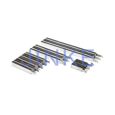
This type named as Resettable Fuse PPTC STRAP JK-P SERIES is widely used,Portable media player battery packs;digital camera battery packs;Computer battery packs;Mobile radio battery packs;Tablet PC battery packs,etc.
Main parameters of PTC thermistor.
1) Rated zero power resistance (R25 or Rn): Refers to the zero power resistance at 25 ° C unless otherwise specified.
2) Minimum resistance (Rmin): refers to the minimum resistance value corresponding to the temperature curve starting from normal temperature 25 ℃.
3) Temperature at the minimum resistance (Tmin): The temperature when the minimum resistance Rmin appears.
4) Switching temperature (TC): The temperature when the resistance value starts to increase stepwise is called the switching temperature, that is, when the resistance value increases to 2 times
The temperature corresponding to the minimum resistance (Rmin) is also called the Curie temperature.
RTC2 = 2 × Rmin
5) Maximum working voltage (Umax): the maximum voltage that the PTC thermistor can sustain under the maximum allowable ambient temperature.
6) Maximum current (Int): refers to the maximum current allowed to pass through the PTC thermistor under the maximum operating voltage.
7) Non-operating current (It): The non-operating current is the rated current or the holding current, which refers to the maximum current that does not cause the PTC thermistor to show a high resistance state under the specified time and temperature conditions.
8) Operating current (It: refers to the minimum current when the resistance value of the PTC thermistor increases stepwise under the specified time and temperature conditions.
9) Temperature range under maximum voltage: The ambient temperature range under which PTC can still work continuously under the maximum voltage, generally 10 ~ + 60 ℃.
10) Dissipation coefficient (δ): The ratio of the power dissipation change of the PTC thermistor to the corresponding temperature change of the component is called dissipation
Coefficient (mW / ° C).
δ = P / (T-Tr,)
11) Withstand voltage value: refers to the maximum voltage that the PTC thermistor can withstand under the specified time and temperature conditions.If this voltage is exceeded, the PTC thermistor will breakdown.
12) Thermal time constant (τ): The time required for the PTC thermistor to change from its own temperature to 63.2% of the difference from the ambient temperature in still air.
13) Residual current (lr): Refers to the current under thermal equilibrium after the PTC thermistor resistance jumps at the maximum operating voltage.
14) Temperature coefficient (a): The temperature coefficient of the PTC thermistor is defined as the relative change in resistance caused by temperature changes, that is,
a = (lgR2: -lgR1,) / lge (T2-T1)
In the formula: The temperatures corresponding to R and R2 are T and T2, which are 10 ° C and 25 ° C higher than the Curie temperature, respectively.
The larger the temperature coefficient, the more sensitive the PTC thermistor responds to temperature changes, and the greater the rate of change in resistance. Example: Thermistor with 1000 at normal temperature (25 ℃), the resistance changes by 0.3% for every 1 ℃ change in temperature. When the temperature rises from 25 ℃ to 105 ℃, the resistance changes from 1000Ω to 1000 × [1 + 0.3% ~ (105-25)] = 1240Ω
15) Surface temperature (T surf): Refers to the temperature of the surface of the PTC thermistor when the PTC thermistor is at a specified voltage and has been in thermal equilibrium with the surrounding environment for a long time.
16) Rated voltage (UN): The rated voltage is at the maximum operating voltage Umax. The following supply voltage is usually Umax = UN + 15%.
Contact
Supplier
Agriculture Machinery & Equipment
Apparel & Textile Machinery
Building Material Machinery
Chemical Machinery & Equipment
Energy & Mineral Equipment
Engineering & Construction Machinery
Food & Beverage Machinery
Home Product Making Machinery
Industry Laser Equipment
Machine Tool Equipment
Metal & Metallurgy Machinery
Other Machinery & Industry Equipment
Packaging Machine
Paper Production Machinery
Plastic & Rubber Machinery
Printing Machine
Woodworking Machinery
Environmental Machinery
Machinery Accessories
Material Handling Equipment
Welding Equipment
Cleaning Equipments
Commercial Machinery
Air-Compressors & Parts