Products Info
HOME> Machinery > Refrigeration & Heat Exchange Equipment > DIP Resettable Fuse 60V PPTC JK60 SERIES >
DIP Resettable Fuse  60V PPTC  JK60 SERIES

DIP Resettable Fuse 60V PPTC JK60 SERIES

Brand Name:
jk
Place of Origin:
china
Material:
polymer
Certification:
ul,tuv
OEM/ODM Availability:
yes
Delivery Time:
ship in 15 days after payment
Start Port:
shenzhen
Supply Ability:
10000000 pieces/month
MOQ:
10--100000
Payment Terms:
l/c, d/a, d/p, t/t, western union, moneygram, oa
Breaking Capacity:
high
Safety Standards:
csa
Usage:
resettable
Mounting type:
smd
Supplier Info.
Registration Date: 2009
Country / Region: guangdong / China
City: shenzhen
Main Products: pptc resettable fuse, ceramic ptc, ptc heating element suppliers
Product Detail


Jinke-Best PPTC Fuse Polyswitch Resettable Devices - Jinke Polymer Ptc

Packaging Quantity & Features


◇ JK60-005~JK60-110 1000Pcs/Bag  or 2000Pcs/Box
◆ JK60-135~JK60-200   500 Pcs/Bag
◇ JK60-250~JK60-500   200 Pcs/Bag
◆ RoHS Compliant & Halogen Free
◇ Radial-leaded Devices
◆ Cured,flame retardant epoxy polymer insulating material meets UL94V-0 requirements
◇ Operation Current: 0.05A~5A ,Maximum Voltage: 60Vdc,Operating Temperature:-40℃ TO 85℃
◆ Agency recognition:UL、TUV


❈ Product Video


❈ Product Dimensions


Jinke-Best PPTC Fuse Polyswitch Resettable Devices - Jinke Polymer Ptc-1


Model

Dimensions(mm)

Lead material

Shape

A(MAX)

B(MAX)

C(MAX)

D(TYP)

Tinned metal(mm)

Fig

JK60-005

5.0

8.5

3.0

5.1

24AWG/Φ0.5

1

JK60-010

5.5

9.5

3.0

5.1

24AWG/Φ0.5

1

JK60-017

7.4

12.7

3.0

5.1

24AWG/Φ0.5

1

JK60-020

7.4

12.7

3.0

5.1

24AWG/Φ0.5

1

JK60-025

7.4

12.7

3.0

5.1

24AWG/Φ0.5

1

JK60-030

7.4

13.0

3.0

5.1

24AWG/Φ0.5

1

JK60-040

7.8

16.2

3.0

5.1

24AWG/Φ0.5

1

JK60-050

7.8

16.2

3.0

5.1

24AWG/Φ0.5

1

JK60-065

9.7

17.8

3.0

5.1

22AWG/Φ0.6

1

JK60-075

10.4

18.4

3.0

5.1

22AWG/Φ0.6

1

JK60-090

11.7

18.4

3.0

5.1

22AWG/Φ0.6

1

JK60-110

13.0

18.0

3.0

5.1

20 AWG/Φ0.8

2

JK60-135

14.5

19.6

3.0

5.1

20 AWG/Φ0.8

2

JK60-160

16.3

21.3

3.0

5.1

20 AWG/Φ0.8

2

JK60-185

17.8

22.9

3.0

5.1

20 AWG/Φ0.8

2

JK60-200

17.8

22.9

3.0

5.1

20 AWG/Φ0.8

2

JK60-250

21.3

26.4

3.0

10.2

20 AWG/Φ0.8

2

JK60-300

21.3

26.4

3.0

10.2

20 AWG/Φ0.8

2

JK60-375

28.5

33.5

3.0

10.2

20    AWG/Φ0.8

2

JK60-500

28.5

33.5

3.0

10.2

20    AWG/Φ0.8

2

Thermal Derating Chart-IH(A)


Model

Maximum ambient operating temperature(℃)

-40℃

-20℃

0℃

25℃

30℃

40℃

50℃

60℃

70℃

85℃

JK60 series

147%

136%

119%

100%

90%

81%

72%

63%

54%

40%

Electrical Characteristics

IH=Hold current:Maximum current at which the device will not interruptin 25℃ still air.
IT=Trip current:Minimum current at which the device from low resistance to high resistance in 25℃ still air.
VMAX=Maximum continuous voltage device can withstand without damage at rated current.
IMAX=Maximum fault current device can withstand without damage at rated voltage.
Maximum Time-to-trip:Maximum time to trip at assigned current.
PD=Typical power dissipation:Typical amount of power dissipated from the device when in 25℃ still air environment.
RMIN=Minimum resistance of device at 25℃ prior to tripping.
RMAX=Maximum resistance of device at 25℃ prior to tripping.


Model


IH(A)


IT(A)

VMAX

IMAX

PD

Maximum Time-to-Trip

Resistance(Ω)

V(DC)

A

W

Current(A)

Time(S)

RMIN

RMAX

JK60-005

0.05

0.15

60

40

0.26

0.25

8.0

7.3

20

JK60-010

0.10

0.3

60

40

0.38

0.5

5.0

2.5

7.5

JK60-017

0.17

0.34

60

40

0.48

0.85

5.0

2

5.21

JK60-020

0.2

0.4

60

40

0.41

1.0

5.0

1.5

2.84

JK60-025

0.25

0.5

60

40

0.45

1.25

5.0

1.0

1.95

JK60-030

0.30

0.6

60

40

0.49

1.5

5.0

0.76

1.38

JK60-040

0.40

0.8

60

40

0.56

2.0

5.0

0.45

0.88

JK60-050

0.50

1.0

60

40

0.77

2.5

5.0

0.40

0.79

JK60-065

0.65

1.3

60

40

0.88

3.25

5.0

0.31

0.50

JK60-075

0.75

1.5

60

40

0.92

3.75

5.0

0.25

0.42

JK60-090

0.90

1.8

60

40

0.99

4.5

5.0

0.20

0.33

JK60-110

1.10

2.2

60

40

1.5

5.5

8.0

0.15

0.27

JK60-135

1.35

2.7

60

40

1.7

6.75

8.0

0.12

0.21

JK60-160

1.60

3.2

60

40

1.9

8.0

8.0

0.09

0.16

JK60-185

1.85

3.7

60

40

2.1

9.25

8.0

0.08

0.14

JK60-200

2.00

4.0

60

40

2.3

10.0

8.0

0.07

0.14

JK60-250

2.50

5.0

60

40

2.5

12.5

8.0

0.05

0.10

JK60-300

3.00

6.0

60

40

2.8

15.0

8.0

0.04

0.08

JK60-375

3.75

7.5

60

40

3.2

18.75

24.0

0.03

0.06

JK60-500

5.00

10

60

40

3.5

25.0

24.0

0.02

0.06

undefined
JK60 Series Specification


❈ Application Scope;


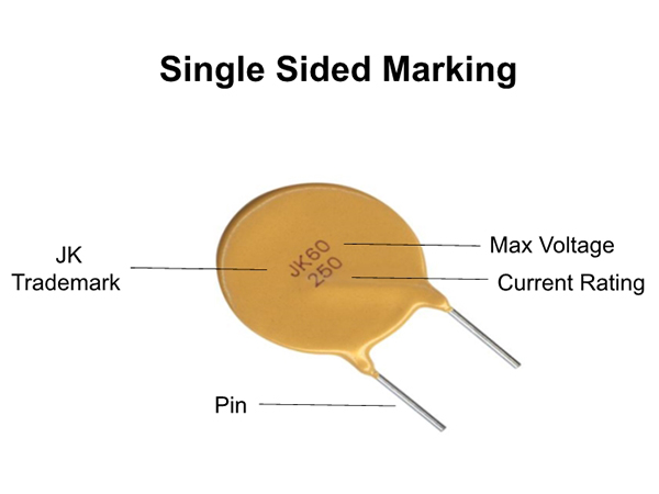
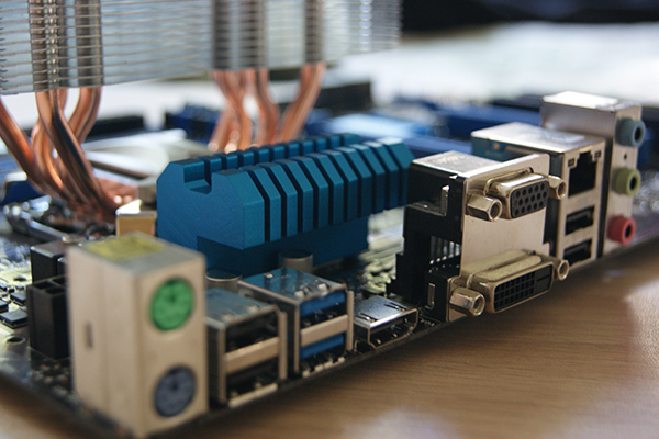
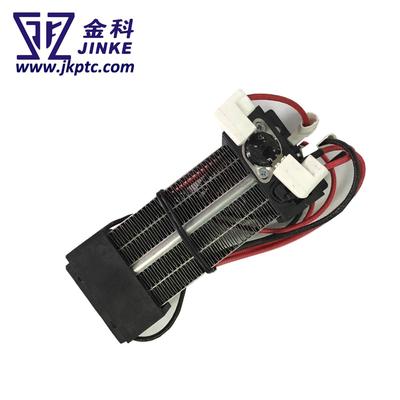
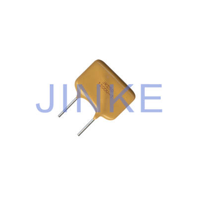
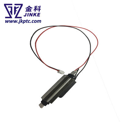
This type named as Resettable Fuse PPTC DIP JK60 Series is widely used,Computers & peripherals;Motor protection;Automotive applications;USB hubs,ports and peripherals;General electronics,etc
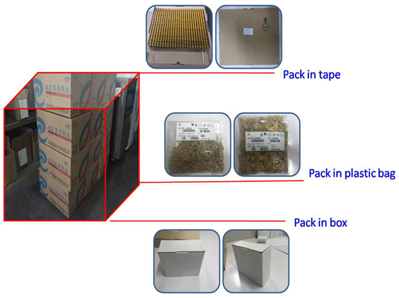

Jinke-Best PPTC Fuse Polyswitch Resettable Devices - Jinke Polymer Ptc-3
Jinke-Best PPTC Fuse Polyswitch Resettable Devices - Jinke Polymer Ptc-4
Jinke-Best PPTC Fuse Polyswitch Resettable Devices - Jinke Polymer Ptc-5
Jinke-Best PPTC Fuse Polyswitch Resettable Devices - Jinke Polymer Ptc-6
❈ Product Packaging


Jinke-Best PPTC Fuse Polyswitch Resettable Devices - Jinke Polymer Ptc-7


❈ Product Certificate

Jinke-Best PPTC Fuse Polyswitch Resettable Devices - Jinke Polymer Ptc-8


PPTC ------ Polymer resettable fuse is composed of polymer matrix and carbon black particles that make it conductive. Because the polymer resettable fuse is a conductor, a current will flow through it. When an overcurrent flows through the polymer resettable fuse, the heat (I2R) generated will cause it to expand. As a result, carbon black particles will separate and the resistance of the polymer resettable fuse will increase. This will cause polymer resettable fuses to generate heat faster and expand even more, further increasing resistance. When the temperature reaches 125 ° C, the resistance changes significantly, which reduces the current significantly. The small current flowing through the polymer resettable fuse at this time is sufficient to keep it at this temperature and in a high resistance state. After the fault is cleared, the polymer resets the fuse to its original shape and reconnects the carbon black particles, thereby reducing the resistance to a level with a specified holding current. The above process can be repeated multiple times.


The operating principle of the PPTC recoverable fuse is a dynamic balance of energy. The current flowing through the PPTC element generates heat due to the relationship of the PPTC. The generated heat is totally or partially radiated to the environment. Without the emitted heat, the PPTC element will be improved temperature.


The temperature during normal operation is relatively low, and the heat generated and heat radiated reaches equilibrium. The PPTC element is in a low resistance state, and the PPTC does not operate. When the current flowing through the PPTC element increases or the ambient temperature increases, but if the balance between the generated heat and the emitted heat is reached, the PPTC still does not operate. When the current or ambient temperature increases, the PPTC will reach a higher temperature. If the current or ambient temperature continues to increase at this time, the heat generated will be greater than the heat emitted, which will cause the temperature of the PPTC component to increase sharply. At this stage, a small temperature change will cause a significant increase in resistance. At this time, the PPTC component is at High resistance protection status.


Contact

Supplier

Contact us
Tell us your Buying Requirements