◪Perfect combination of PLC and high performance vector inverter on professional crane function
◪Strong startup torque under low frequency
◪Reliable brake control to eliminate glide-hook
◪Smooth and reliable lifting speed
◪Greater overload capacity
◪Better power optimization
◪Position processing and intelligent deceleration
◪Standard international bus communication and optimized communication format
◪Safe and sound keyboard operation
◪Comprehensive monitoring and protection with fault


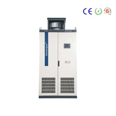
Inverter for Hoist/Crane/Trolley/Gantry
Delivery Time:
with 20 days after deposit
Port of loading:
shenzhen,shanghai
Sample provide:
yes
Sample free:
yes
Sample freight payer:
buyer
Term of payment:
t/t,l/c
Delivery Time:
with 20 days after deposit
Port of loading:
shenzhen,shanghai
Sample provide:
yes
Supplier Info.
Company Name: Shenzhen V&T Technologies Co.Ltd.
Registration Date:
2006
Country / Region:
guangdong / China
City:
shenzhen
Main Products:
variable frequency drive,servo drive,ev motor controller
Product Detail
Representative Industry and Applicable Machine
Port, Ship, Marine Engineering, Mining, Construction, Metallurgy, Factories and other industries.
Port Wheel Crane, Gantry Crane, Tower Crane, Hoist, Electric Hoist, Crane, Mine Hoist, Winch, Grab Control and other machines.
Product Overview

Product Overview
V6-G and V5-G series are special inverter for high performance hoist.
The product adopts the torque vector control technology with the current international advanced technology.
This product has excellent torque control, reliable brake control on time and sequence, speed monitoring, torque monitoring, power optimization, position processing, intelligent deceleration and other functions. It greatly guarantees the safety, reliability and high efficiency of the crane.
V6 - G is suitable for motor with an encoder.
V5 - G is suitable for motor without an encoder.
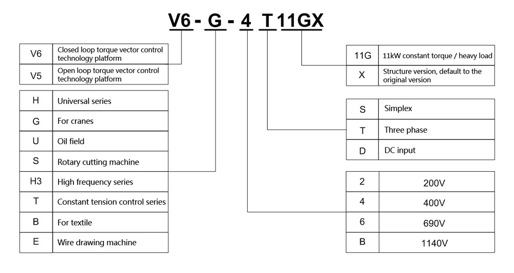
Model Explanation
Product Catalogue
◪V6−G−4T□□□GX and V5−G−4T□□□GX 3 Phase 400V Constant Torque/Heavy-duty Applications
Power(kW) | 0.4 | 0.75 | 1.5 | 2.2 | 3.7 | 5.5 | 7.5 | 11 | 15 | 18.5 | 22 | 30 | 37 | 45 | 55 | ||||||||||||||||||||||||||||||||||||||
Motor(kW) | 0.4 | 0.75 | 1.5 | 2.2 | 3.7 | 5.5 | 7.5 | 11 | 15 | 18.5 | 22 | 30 | 37 | 45 | 55 | ||||||||||||||||||||||||||||||||||||||
Output | Voltage(V) | 3 phase 0~Rated Voltage | |||||||||||||||||||||||||||||||||||||||||||||||||||
Rated Current(A) | 2.5 | 3.8 | 5.5 | 9 | 13 | 17 | 24 | 30 | 39 | 45 | 60 | 75 | 91 | 112 | 150 | ||||||||||||||||||||||||||||||||||||||
Overload capacity | 150% 1min,180% 10 second, 200% 0.5 second,interval: 10 minutes (inverse time lag feature) | ||||||||||||||||||||||||||||||||||||||||||||||||||||
Input | Voltage/ frequency | 3 phase 380V~480V;50Hz/60Hz | |||||||||||||||||||||||||||||||||||||||||||||||||||
Allowable voltage range | 323V~528V;Voltage imbalance :≤3% ;allowable frequency fluctuation:±5% | ||||||||||||||||||||||||||||||||||||||||||||||||||||
Rated Current(A) | 2.8 | 4.2 | 6.1 | 10 | 15 | 19 | 26 | 33 | 43 | 50 | 66 | 83 | 100 | 123 | 165 | ||||||||||||||||||||||||||||||||||||||
Braking unit | Built-in as standard | ||||||||||||||||||||||||||||||||||||||||||||||||||||
IP | IP20 | ||||||||||||||||||||||||||||||||||||||||||||||||||||
Cooling mode | Natural air cooling | Forced air cooling | |||||||||||||||||||||||||||||||||||||||||||||||||||
Power(kW) | 75 | 90 | 110 | 132 | 160 | 185 | 200 | 220 | 250 | 280 | 315 | 355 | 400 | 450 | |||||||||||||||||||||||||||||||||||||||
Motor(kW) | 75 | 90 | 110 | 132 | 160 | 185 | 200 | 220 | 250 | 280 | 315 | 355 | 400 | 450 | |||||||||||||||||||||||||||||||||||||||
Output | Voltage(V) | 3 phase 0~Rated Voltage | |||||||||||||||||||||||||||||||||||||||||||||||||||
Rated Current(A) | 176 | 210 | 253 | 304 | 350 | 380 | 426 | 470 | 520 | 600 | 650 | 690 | 775 | 860 | |||||||||||||||||||||||||||||||||||||||
Overload capacity | 150% 1min,180% 10 second, 200% 0.5 second,interval: 10 minutes (inverse time lag feature) | ||||||||||||||||||||||||||||||||||||||||||||||||||||
Input | Voltage/ frequency | 3 phase 380V~480V;50Hz/60Hz | |||||||||||||||||||||||||||||||||||||||||||||||||||
Allowable voltage range | 323V~528V;Voltage imbalance :≤3% ;allowable frequency fluctuation:±5% | ||||||||||||||||||||||||||||||||||||||||||||||||||||
Rated Current (A) | 160* | 196* | 232* | 282* | 326* | 352* | 385* | 437* | 491* | 580* | 624* | 670* | 755* | 840* |
| ||||||||||||||||||||||||||||||||||||||
Braking unit | External braking unit needed | ||||||||||||||||||||||||||||||||||||||||||||||||||||
IP | IP20 | ||||||||||||||||||||||||||||||||||||||||||||||||||||
Cooling mode | Forced air cooling | ||||||||||||||||||||||||||||||||||||||||||||||||||||
* V6-G-4T75GX, V5-G-4T75GX and higher power grade are standard external DC reactor
* V6-G-4T55GX, V5-G-4T55GX and lower power grade are standard Built-in brake units
* V6-G-4T75GX, V5-G-4T75GX and higher power grade require an external brake unit
Installation Dimension
◪Product appearance, installation dimensions, approximate weight
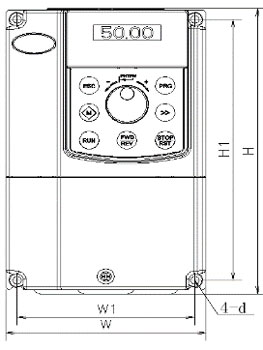
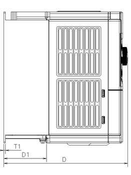
V6/ V5-G-4T5.5GX and lower power grade
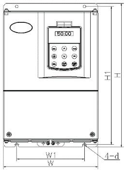
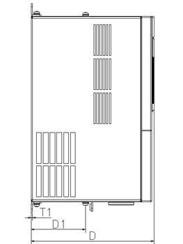
V6/V5-G−4T7.5GX and higher power grade
◪Appearance, Installation Dimensions
Voltage(V) | Model | Appearance, Installation Dimensions(mm) | Weight(kg) | |||||||
W | H | D | W1 | H1 | D1 | T1 | Hole d | |||
400V | V6/V5−G−4T0.4GX | 118 | 190 | 175 | 105 | 173 | 60.5 | 4 | 5.5 | 2.6 |
V6/V5−G−4T0.75GX | ||||||||||
V6/V5−G−4T1.5GX | ||||||||||
V6/V5−G−4T2.2GX | ||||||||||
V6/V5−G−4T3.7GX | 155 | 249 | 185 | 136 | 232 | 69 | 8 | 5.5 | 3 | |
V6/V5−G−4T5.5GX | ||||||||||
V6/V5−G−4T7.5GX | 210 | 337 | 200 | 150 | 324 | 107.5 | 2.5 | 7 | 8.5 | |
V6/V5−G−4T11GX | ||||||||||
V6/V5−G−4T15GX | 285 | 440 | 220 | 200 | 425 | 107.5 | 2.5 | 7 | 17 | |
V6/V5−G−4T18.5GX | ||||||||||
V6/V5−G−4T22GX | ||||||||||
V6/V5−G−4T30GX | 315 | 575 | 227 | 220 | 553 | 123.5 | 2.5 | 10 | 25 | |
V6/V5−G−4T37GX | ||||||||||
V6/V5−G−4T45GX | 400 | 615 | 265 | 270 | 590 | 123.5 | 3.0 | 10 | 35 | |
V6/V5−G−4T55GX | ||||||||||
V6/V5−G−4T75GX | 465 | 745 | 325 | 343 | 715 | 156 | 3.0 | 12 | 55 | |
V6/V5−G−4T90GX | ||||||||||
V6/V5−G−4T110GX | 540 | 890 | 385 | 370 | 855 | 205.5 | 4.0 | 14 | 85 | |
V6/V5−G−4T132GX | ||||||||||
V6/V5−G−4T160GX | ||||||||||
V6/V5−G−4T185GX | ||||||||||
V6/V5−G−4T200GX | 700 | 1010 | 385 | 520 | 977 | 210 | 4.0 | 14 | 125 | |
V6/V5−G−4T220GX | ||||||||||
V6/V5−G−4T250GX | ||||||||||
V6/V5−G−4T280GX | 810 | 1358 | 425 | 520 | 1300 | 210 | 4.0 | 14 | 215 | |
V6/V5−G−4T315GX | ||||||||||
V6/V5−G−4T355GX | ||||||||||
V6/V5−G−4T400GX | ||||||||||
V6/V5−G−4T450GX | ||||||||||
Note: the detailed definition of W, H, D, W1, H1, D1, T1 and installation hole D should refer to the standard specification.
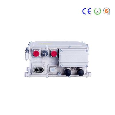
Applications


The control system of electric vehicle motor is generally composed of motor, power inverter, sensor and Controller
Electric vehicle controller.
The electric vehicle motor control system should choose a more suitable synchronization system according to the complexity of its control algorithm. Many simple ones have replacement microcontroller controllers, and complex ones can use DSP controllers. The latest motor-driven dedicated chips can meet the motor control needs of some auxiliary systems. For electric vehicle motor controllers, DSP processors are generally suitable.
The control circuit mainly includes the following parts: control chip and its driving system, AD sampling system, power module and its driving system, hardware protection system, position detection system, bus support capacitor, etc.
The main power circuit uses the inverter full bridge as shown in Figure 4-32. The main power switching device is IG-BT. Under high-current and high-frequency switching conditions, the stray inductance from the electrolytic capacitor to the power switch module affects the temperature of the power circuit and the peak voltage on the module affects the series connection. Therefore, the alternating bus substrate is used to make the stray inductance of the circuit small To adapt to the characteristics of the control system low voltage, high current work.
Contact
Supplier
Contact us
Tell us your Buying Requirements


You Might Also Like