◪Higher saving-energy effect and Less reactive current.
◪Outdoor digital control cabinet, thermostatic control cabinet suit high and low temperature ambient for long-term reliable work..
◪Excellent control performance for open-loop vector control, accurate speed identification and rotor flux orientation, and torque can respond quickly and operate stably at 0.25hz load change.
◪Excellent current and voltage control technology, repeatedly and alternately accelerated and decelerated with 0.1s instruction, and inverter operates stably.
◪Wide voltage range, low voltage under fluctuated power, continuous working, strong adaptability.
◪Convenient and continuous to adjust speed, perfect torque compensation function, normal to start motor with powerful power.
◪Mature power balance scheme can effectively solve power distribution in multi-point transmission.


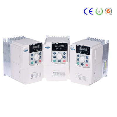
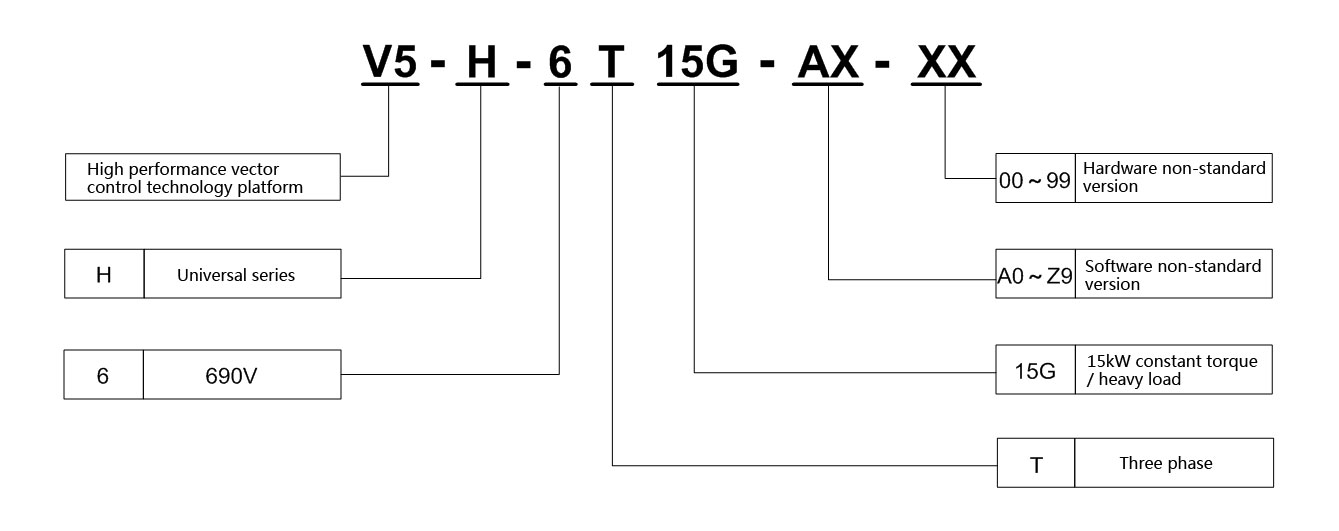
V5 - H - 6T High-performance Vector Control Inverter
Representative Industry
Oilfield, Explosion-proof Products, Mining Winch, Belt transport machine and so on.
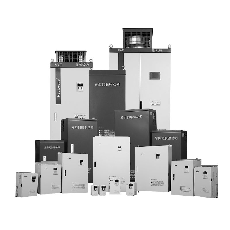
Product Overview
V5-H-6T is a high - performance vector control inverter.
The product adopts the open-loop vector control technology with the current international advanced technology, which has the same excellent control performance with the international high-end driver, At the same time, it is combined with the use characteristics of China, and it further strengthened the reliability and environmental adaptability of the product, as well as the customized and professional design. This greatly meet the needs of various transmission applications.
◪V5−H−6T□□□G 3 Phase 690V Constant Torque/Heavy-duty Applications
Power(kW) | 15 | 18.5 | 22 | 30 | 37 | 45 | 55 | 75 | 90 | 110 | 132 | 160 | 185 | 200 | 220 | |||||
Motor(kW) | 15 | 18.5 | 22 | 30 | 37 | 45 | 55 | 75 | 90 | 110 | 132 | 160 | 185 | 200 | 220 | |||||
Output | Voltage(V) | 3 phase 0~Rated Voltage | ||||||||||||||||||
Rated Current(A) | 20 | 25 | 28 | 35 | 45 | 52 | 65 | 86 | 98 | 120 | 150 | 176 | 204 | 220 | 245 | |||||
Overload capacity | 150% 1min,180% 10 second, 200% 0.5 second,interval: 10 minutes (inverse time lag feature) | |||||||||||||||||||
Input | Voltage/ frequency | 3 phase 690V~790V;50Hz/60Hz | ||||||||||||||||||
Allowable voltage range | 587V~793V;Voltage imbalance:≤3% ;allowable frequency fluctuation:±5% | |||||||||||||||||||
Rated Current(A) | 25 | 30 | 35 | 40 | 47 | 52 | 65 | 85 | 96 | 116 | 145 | 168 | 196 | 210 | 230 | |||||
*Braking unit | Built-in as standard | External braking unit needed | ||||||||||||||||||
IP | IP20 | |||||||||||||||||||
Cooling mode | Forced air cooling | |||||||||||||||||||
Power(kW) | 250 | 280 | 315 | 355 | 400 | 450 | 500 | 560 | 630 |
|
|
|
|
|
| |||||
Motor(kW) | 250 | 280 | 315 | 355 | 400 | 450 | 500 | 560 | 630 |
|
|
|
|
|
| |||||
Output | Voltage(V) | 3 phase 0~Rated Voltage | ||||||||||||||||||
Rated Current(A) | 275 | 325 | 350 | 395 | 435 | 490 | 545 | 600 | 680 |
|
|
|
|
|
| |||||
Overload capacity | 150% 1min,180% 10 second, 200% 0.5 second,interval: 10 minutes (inverse time lag feature) | |||||||||||||||||||
Input | Voltage/ frequency | 3 phase 690V~790V;50Hz/60Hz | ||||||||||||||||||
Allowable voltage range | 587V~793V;Voltage imbalance:≤3% ;allowable frequency fluctuation:±5% | |||||||||||||||||||
Rated Current(A) | 255 | 290 | 335 | 378 | 415 | 466 | 520 | 580 | 655 |
|
|
|
|
|
| |||||
*Braking unit | External braking unit needed | |||||||||||||||||||
IP | IP20 | |||||||||||||||||||
Cooling mode | Forced air cooling | |||||||||||||||||||
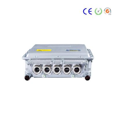
V5−H−6T90G And lower power grade
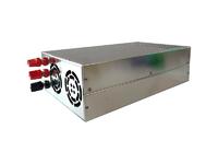
V5−H−6T110G And higher power grade(accompany with pedestal)
V5−H−6T110G And higher power grade(no pedestal)
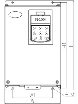
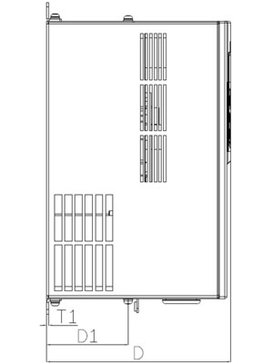
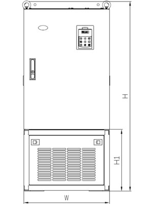
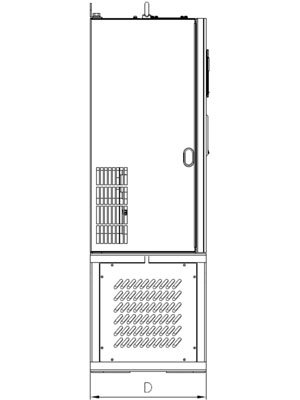
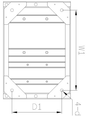
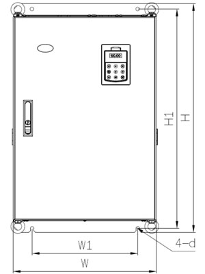
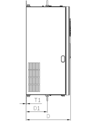
◪Product appearance, installation dimensions, approximate weight
Voltage | power(kW) | pedestal | Appearance size(mm) | Installation Dimensions(mm) | Weight(kg) | ||||||
W | H | D | W1 | H1 | D1 | T1 | Hole d | ||||
690V | 15~30 | No | 285 | 440 | 220 | 200 | 425 | 107.5 | 2.5 | 7 | 17 |
37~55 | No | 315 | 575 | 227 | 220 | 553 | 123.5 | 2.5 | 10 | 25 | |
75~90 | No | 400 | 615 | 265 | 270 | 590 | 123.5 | 3.0 | 10 | 35 | |
110~132 | yes | 465 | 1042 | 325 | 382 | 339 | 238 | — | 14 | — | |
No | 465 | 745 | 325 | 343 | 715 | 156 | 3.0 | 12 | 55 | ||
160~220 | yes | 540 | 1206 | 385 | 459 | 365 | 300 | — | 14 | — | |
No | 540 | 890 | 385 | 370 | 855 | 205.5 | 4.0 | 14 | 85 | ||
250~355 | yes | 700 | 1380 | 385 | 614 | 412 | 294 | — | 15 | — | |
No | 700 | 1010 | 385 | 520 | 977 | 210 | 4.0 | 14 | 125 | ||
400~630 | yes | 810 | 1698 | 425 | 728 | 418 | 339 | — | 15 | — | |
No | 810 | 1358 | 425 | 520 | 1300 | 210 | 4.0 | 14 | 215 | ||
Routine maintenance editor
With the continuous development of the automation field, the application of frequency converters has penetrated into various fields and industries, and the frequency converters are constantly being introduced, with more and more powerful functions and correspondingly higher and higher reliability. However, if it is used improperly, if it is operated incorrectly, or if maintenance is not performed in a timely manner, failures or changes in operating conditions may shorten the service life of the equipment. Therefore, the daily maintenance and repair work is particularly important.
One. Note: The operator must be familiar with the basic working principle and functional characteristics of the inverter, and have basic knowledge of electrician operation. Before inspecting and maintaining the inverter, the main power supply of the equipment must be completely cut off; and wait until the inverter lamp is completely off.
two. Daily inspection items: Check the temperature and humidity of the surrounding environment before the inverter is powered on. If the temperature is too high, it will cause the inverter to overheat and alarm. If it is serious, it will directly cause the inverter power device to be damaged and the circuit to be short-circuited. Causes a direct short circuit inside the inverter. When the inverter is running, pay attention to whether its cooling system is normal, such as: whether the exhaust air is smooth, and whether the fan has abnormal sound. Generally, inverters with a higher protection level, such as inverters with an IP20 or higher, can be installed directly open. Inverters with an IP20 or lower should be installed in a cabinet, so how the heat dissipation effect of the inverter cabinet directly affects the normal operation of the inverter.
three. Regular maintenance Clean the air filter cooling duct and internal dust. Check whether the screws, bolts, and plug-ins are loose, and whether there is a short circuit between the input and output reactors to the ground and the phase resistance, which should normally be greater than several tens of megohms. Whether the conductors and insulators are corroded, if necessary, wipe them clean with alcohol in time. If conditions permit, use an oscilloscope to measure the smoothness of the voltage output from the switching power supply, such as 5V, 12V, 15V, 24V and other voltages. Measure the square wave of each waveform of the drive circuit for distortion. Whether the UVW interphase waveform is a sine wave. If the contact of the contactor has traces of ignition, it is necessary to replace it with a new product of the same model or larger than the original capacity; confirm the correctness of the control voltage and perform a sequence protection operation test; confirm that the protection display circuit is normal; Balance of output voltage during operation. Regular inspections are recommended and should be carried out once a year.
four. Replacement of spare parts The inverter is composed of various components, some of which will gradually degrade and age after long-term work. This is also the main reason for the failure of the inverter. In order to ensure the long-term normal operation of the equipment, the following components should be replaced regularly:
1. Cooling fan The power module of the inverter is the component that generates the most heat. The heat generated by continuous operation must be discharged in time. The life of a general fan is about 10Kh-40Kh. According to the continuous operation of the inverter, the fan should be replaced once every 2-3 years. Direct cooling fans are divided into two lines and three lines. One line of the second line fan is positive, and the other line is negative. Do not connect the fan incorrectly when replacing. There is also a detection wire outside the negative pole. Be careful when replacing it, otherwise it will cause the inverter to overheat. The AC fan is generally divided into 220V and 380V. Do not mistake the voltage level when replacing it.
2. Filter capacitor Intermediate circuit filter capacitor: Also called electrolytic capacitor, its main function is to smooth the DC voltage and absorb the low-frequency harmonics in the DC. The heat generated by its continuous operation plus the heat generated by the inverter itself will speed up the drying of its electrolyte. , Directly affect the size of its capacity. The service life of the capacitor is 5 years under normal conditions. It is recommended to check the capacity of the capacitor at least once a year. Generally, the capacity needs to be replaced if it is reduced by more than 20%.
Contact
Supplier