


FEATURES:
² Low capacitance of 100 pF or less.
² Molding compound flammability rating: UL94V-O.
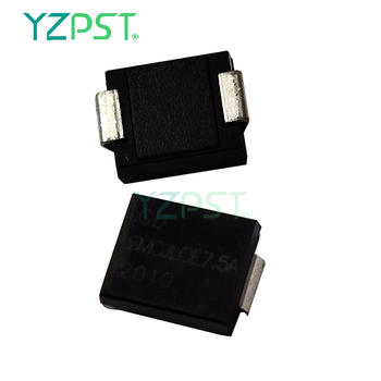
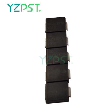
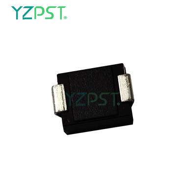
² Two different terminations available in C-bend (modified J-bend with DO-214AB) or Gull-wing(DO-215AB).
² Screening available in reference to MIL-PRF-19500. Refer to High Reliability Up-Screened Plastic Products Portfolio for more details on the screening options.(See part nomenclature for all available options.)
² RoHS compliant versions available.
APPLICATIONS / BENEFITS:
² 1500 watts peak pulse power at 10/1000 µs.
² Low capacitance for high frequency data line protection to 1 MHz.
² Protection for aircraft fast data rate lines up to level 5 waveform 4 and level 2 waveform 5A in
² RTCA/DO-160D (also see MicroNote 130) & ARINC 429 with bit rates of 100 kb/s (per ARINC 429,
² Part 1, par 2.4.1.1).
² IEC61000-4-2 ESD 15 kV (air), 8 kV (contact).
² IEC61000-4-5 (lightning) as further detailed in LCE6.5 thru LCE170A data sheet.
² T1/E1 line cards.
² Base stations, WAN & XDSL interfaces.
² CSU/DSU equipment.
ABSOLUTE MAXIMUM RATINGS (TA=25ºC, RH=45%-75%, unless otherwise noted)
Parameter | Symbol | Value | Unit |
Storage temperature range | Tstg | -65 to +150 | ℃ |
Operating junction temperature range | Tj | -65 to +150 | ℃ |
Thermal Resistance Junction-to-Lead (1) | R JL | 20 | ℃/W |
Steady state power dissipation at TL=75℃ | PM(AV) | 5.0 | W |
Clamping Factor @ Full Rated Power @ 50 % Rated Power | CF | 1.4 1.30 | |
Peak pulse power dissipation on 10/1000μs waveform | PPP | 1500 | W |
t clamping (0 volts to V (BR) min.) |
t clamping | < 5x10 -9 | S |
Notes: 1. Typical junction to lead (tab) at mounting plane.
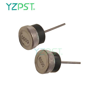
MARKING

ELECTRICAL CHARACTERISTICS (TA=25℃)
Parameter | Test Conditions | Min. | Typ. | Max. | Unit |
Reverse Stand-Off Voltage VWM | 7.5 | V | |||
Maximum Reverse Leakage @VWM ID |
VD= VWM |
250 |
μA | ||
Breakdown Voltage V (BR) @ I (BR) | I (BR)=10mA | 8.33 | 10.2 | V | |
Maximum Capacitance | 0 Volts,f = 1 MHz | 100 | pF | ||
Maximum Peak Pulse Current IPP@10/1000Amps |
10/1000μs |
100 |
A | ||
Maximum Clamping Voltage@IPP VC | 10/1000μs,IT=IPPM | 12.9 | V | ||
Working Inverse Blocking Voltage VWIB | 75 | V | |||
Inverse Blocking Leakage Current IIB | 10 | uA | |||
Peak Inverse Blocking Voltage VPIB | 100 | V |
Contact
Supplier