Features
◇ Lower power consumption by lower resistance
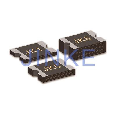
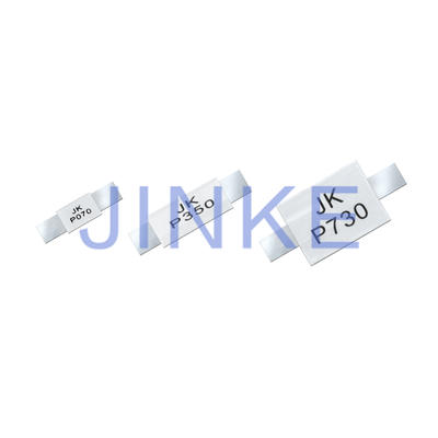
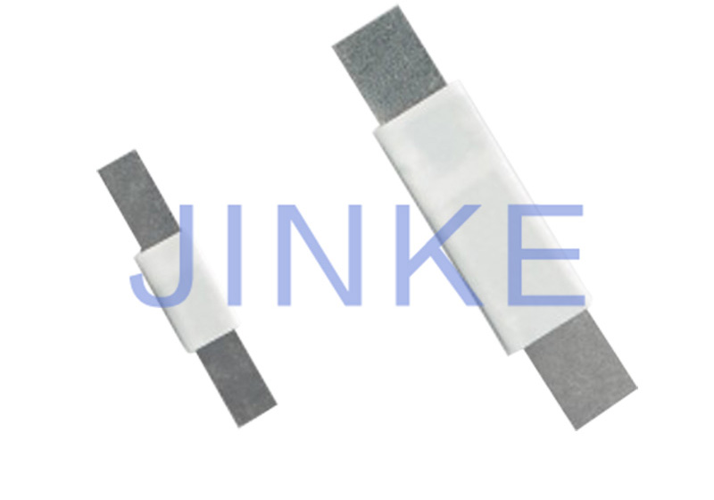
◆ The miniaturized PTC elements leads a flexible design around battery
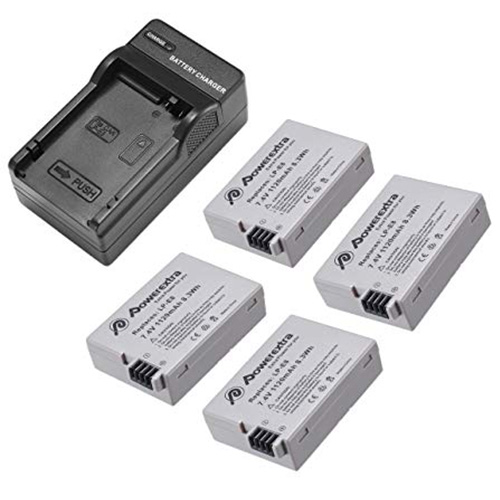
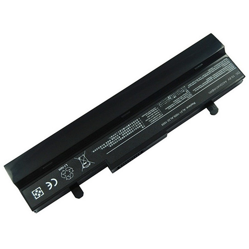
◆ Typical used for protection of Li-ion /Polymer Li-ion battery
◇ Lead-free
◆ Halogen free
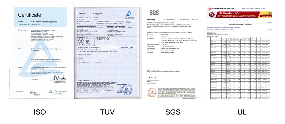
◇ Agency recognition:UL、CSA、TUV


◇ Lower power consumption by lower resistance
◆ The miniaturized PTC elements leads a flexible design around battery
◆ Typical used for protection of Li-ion /Polymer Li-ion battery
◇ Lead-free
◆ Halogen free
◇ Agency recognition:UL、CSA、TUV
❈ Product Video
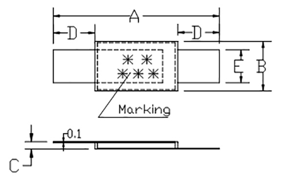
Model | A | B | C | D | E | |||||
Min | Max | Min | Max | Min | Max | Min | Max | Min | Max | |
JK-M120 | 13 | 15 | 3.0 | 3.6 | 0.6 | 1.0 | 3.5 | 5.5 | 2.2 | 2.4 |
JK-M140 | 13 | 15 | 3.0 | 3.6 | 0.6 | 1.0 | 3.5 | 5.5 | 2.2 | 2.4 |
JK-M175 | 13 | 15 | 3.0 | 3.6 | 0.6 | 1.0 | 3.5 | 5.5 | 2.2 | 2.4 |
JK-M190 | 13 | 15 | 3.0 | 3.6 | 0.6 | 1.0 | 3.5 | 5.5 | 2.2 | 2.4 |
JK-M210 | 13 | 15 | 3.0 | 3.6 | 0.6 | 1.0 | 3.5 | 5.5 | 2.2 | 2.4 |
JK-M260 | 13 | 15 | 3.0 | 3.6 | 0.6 | 1.0 | 3.5 | 5.5 | 2.2 | 2.4 |
JK-M270 | 13 | 15 | 3.0 | 3.6 | 0.6 | 1.0 | 3.5 | 5.5 | 2.2 | 2.4 |
JK-M300 | 13 | 15 | 3.0 | 3.6 | 0.6 | 1.0 | 3.5 | 5.5 | 2.2 | 2.4 |
JK-M350 | 14.5 | 17 | 3.0 | 3.6 | 0.6 | 1.0 | 3.5 | 5.5 | 2.2 | 2.4 |
JK-M370 | 14.5 | 17 | 3.0 | 3.6 | 0.6 | 1.0 | 3.5 | 5.5 | 2.2 | 2.4 |
JK-M400 | 14.5 | 17 | 3.0 | 3.6 | 0.6 | 1.0 | 3.5 | 5.5 | 2.2 | 2.4 |
JK-M430 | 14.5 | 17 | 3.0 | 3.6 | 0.6 | 1.0 | 3.5 | 5.5 | 2.2 | 2.4 |
JK-M450 | 21.5 | 23.3 | 3.50 | 3.90 | 0.55 | 1.0 | 4.5 | 6.5 | 2.2 | 2.4 |
JK-M500 | 21.5 | 23.3 | 3.50 | 3.90 | 0.55 | 1.0 | 4.5 | 6.5 | 2.2 | 2.4 |
JK-M550 | 21.5 | 23.3 | 3.50 | 3.90 | 0.55 | 1.0 | 4.5 | 6.5 | 2.2 | 2.4 |
JK-M600 | 20.9 | 23.1 | 4.6 | 5.5 | 0.60 | 1.00 | 4.0 | 6.0 | 3.8 | 4.2 |
JK-M650 | 20.9 | 23.1 | 4.6 | 5.5 | 0.60 | 1.00 | 4.0 | 6.0 | 3.8 | 4.2 |
JK-M700 | 20.9 | 23.1 | 4.6 | 5.5 | 0.60 | 1.00 | 4.0 | 6.0 | 3.8 | 4.2 |
JK-M730 | 20.9 | 23.1 | 4.6 | 5.5 | 0.60 | 1.00 | 4.0 | 6.0 | 3.8 | 4.2 |
JK-M800 | 20.9 | 23.1 | 4.6 | 5.5 | 0.60 | 1.00 | 4.0 | 6.0 | 3.8 | 4.2 |
JK-M850 | 20.9 | 23.1 | 4.6 | 5.5 | 0.60 | 1.00 | 4.0 | 6.0 | 3.8 | 4.2 |
JK-M900 | 20.9 | 23.1 | 4.6 | 5.5 | 0.60 | 1.00 | 4.0 | 6.0 | 3.8 | 4.2 |
JK-M950 | 20.9 | 23.1 | 4.6 | 5.5 | 0.60 | 1.00 | 4.0 | 6.0 | 3.8 | 4.2 |
JK-M1000 | 20.9 | 23.1 | 4.6 | 5.5 | 0.60 | 1.00 | 4.0 | 6.0 | 3.8 | 4.2 |
Thermal Derating Chart-IH(A)
Model | Maximum ambient operating temperature(℃) | |||||||
-40 | -20 | 0 | 25 | 40 | 50 | 60 | 70 | |
JK-M120 | 2.00 | 1.80 | 1.55 | 1.20 | 1.00 | 0.85 | 0.70 | 0.55 |
JK-M140 | 2.40 | 2.10 | 1.80 | 1.40 | 1.14 | 0.97 | 0.80 | 0.63 |
JK-M175 | 3.10 | 2.65 | 2.25 | 1.75 | 1.40 | 1.25 | 1.05 | 0.85 |
JK-M190 | 3.60 | 3.10 | 2.60 | 1.90 | 1.60 | 1.30 | 1.20 | 1.00 |
JK-M210 | 3.60 | 3.20 | 2.80 | 2.10 | 1.84 | 1.40 | 1.34 | 1.10 |
JK-M260 | 4.50 | 3.95 | 3.35 | 2.60 | 2.15 | 1.85 | 1.70 | 1.15 |
JK-M270 | 4.60 | 4.00 | 3.40 | 2.70 | 2.20 | 1.90 | 1.60 | 1.30 |
JK-M300 | 5.20 | 4.50 | 3.85 | 3.00 | 2.45 | 2.10 | 1.75 | 1.40 |
JK-M350 | 5.90 | 5.20 | 4.50 | 3.50 | 2.80 | 2.40 | 2.00 | 1.60 |
JK-M370 | 6.10 | 5.40 | 4.70 | 3.70 | 3.00 | 2.50 | 2.10 | 1.70 |
JK-M400 | 6.20 | 5.50 | 4.80 | 4.00 | 3.30 | 2.80 | 2.50 | 2.00 |
JK-M430 | 6.30 | 5.60 | 4.90 | 4.30 | 3.50 | 3.00 | 2.70 | 2.20 |
JK-M450 | 6.40 | 5.70 | 5.05 | 4.50 | 4.05 | 3.70 | 3.40 | 3.05 |
JK-M500 | 6.95 | 6.20 | 5.60 | 5.00 | 4.50 | 4.10 | 3.80 | 3.40 |
JK-M550 | 7.60 | 6.80 | 6.15 | 5.50 | 4.95 | 4.50 | 4.25 | 3.85 |
JK-M600 | 8.25 | 7.40 | 6.65 | 6.00 | 5.40 | 5.00 | 4.70 | 4.30 |
JK-M650 | 8.90 | 8.05 | 7.20 | 6.50 | 5.80 | 5.45 | 5.10 | 4.70 |
JK-M700 | 9.60 | 8.70 | 7.70 | 7.00 | 6.20 | 5.80 | 5.40 | 5.05 |
JK-M730 | 9.85 | 9.00 | 8.00 | 7.30 | 6.45 | 6.05 | 5.65 | 5.25 |
JK-M800 | 10.40 | 9.80 | 8.80 | 8.00 | 7.00 | 6.60 | 6.20 | 5.80 |
JK-M850 | 11.25 | 10.40 | 9.40 | 8.50 | 7.50 | 7.00 | 6.75 | 6.10 |
JK-M900 | 12.10 | 11.00 | 9.95 | 9.00 | 7.95 | 7.40 | 6.90 | 6.40 |
JK-M950 | 12.60 | 11.50 | 10.0 | 9.50 | 8.40 | 7.90 | 7.25 | 6.75 |
JK-M1000 | 13.15 | 12.00 | 11.00 | 10.00 | 8.90 | 8.40 | 7.65 | 7.10 |
Electrical Characteristics
IH=Hold current:Maximum current at which the device will not interrupt in 25℃ still air.
IT=Trip current:Minimum current at which the device from low resistance to high resistance in 25℃ still air.
VMAX=Maximum continuous voltage device can withstand without damage at rated current.
IMAX=Maximum fault current device can withstand without damage at rated voltage.
Maximum Time-to-trip:Maximum time to trip at assigned current.
PD=Typical power dissipation:Typical amount of power dissipated from the device when in 25℃ still air environment.
RiMIN=Minimum resistance of device at 25℃ prior to tripping.
R1MAX = Maximum device resistance is measured one hour post reflow.
Model | IH | IT | Vmax | Imax | Pd | Maximum Time-to-trip | Rmin | Rmax | R1max | |
(A) | (A) | (V) | (A) | (W) | Current(A) | Time(S) | (Ω) | (Ω) | (Ω) | |
JK-M120 | 1.20 | 3.50 | 10 | 50 | 1.00 | 6.0 | 5.0 | 0.015 | 0.035 | 0.070 |
JK-M140 | 1.40 | 3.60 | 10 | 50 | 1.00 | 7.0 | 5.0 | 0.010 | 0.020 | 0.040 |
JK-M175 | 1.75 | 4.30 | 10 | 50 | 1.00 | 8.75 | 5.0 | 0.009 | 0.018 | 0.036 |
JK-M190 | 1.90 | 4.90 | 10 | 50 | 1.00 | 9.50 | 3.0 | 0.007 | 0.014 | 0.028 |
JK-M210 | 2.10 | 5.60 | 10 | 50 | 1.00 | 10.50 | 3.0 | 0.007 | 0.014 | 0.028 |
JK-M260 | 2.60 | 6.00 | 10 | 50 | 1.00 | 13.00 | 3.0 | 0.006 | 0.014 | 0.028 |
JK-M270 | 2.70 | 6.20 | 10 | 50 | 1.00 | 13.50 | 3.0 | 0.006 | 0.014 | 0.028 |
JK-M300 | 3.00 | 8.00 | 10 | 50 | 1.30 | 15.00 | 3.0 | 0.005 | 0.013 | 0.026 |
JK-M350 | 3.50 | 8.80 | 10 | 50 | 1.30 | 17.50 | 3.0 | 0.005 | 0.013 | 0.026 |
JK-M370 | 3.70 | 9.00 | 10 | 50 | 1.30 | 18.50 | 5.0 | 0.005 | 0.013 | 0.026 |
JK-M400 | 4.00 | 9.60 | 10 | 50 | 1.50 | 20.00 | 5.0 | 0.004 | 0.012 | 0.024 |
JK-M430 | 4.30 | 10.00 | 10 | 50 | 1.50 | 21.50 | 5.0 | 0.004 | 0.012 | 0.024 |
JK-M450 | 4.50 | 10.80 | 10 | 50 | 1.50 | 22.50 | 5.0 | 0.004 | 0.012 | 0.024 |
JK-M500 | 5.00 | 12.00 | 10 | 50 | 1.50 | 25.00 | 5.0 | 0.003 | 0.011 | 0.022 |
JK-M550 | 5.50 | 13.00 | 10 | 50 | 1.50 | 27.50 | 5.0 | 0.003 | 0.011 | 0.022 |
JK-M600 | 6.00 | 13.00 | 10 | 50 | 1.50 | 30.00 | 5.0 | 0.003 | 0.009 | 0.018 |
JK-M650 | 6.50 | 13.00 | 10 | 50 | 1.50 | 32.50 | 5.0 | 0.002 | 0.008 | 0.016 |
JK-M700 | 7.00 | 14.00 | 10 | 50 | 1.50 | 35.00 | 5.0 | 0.002 | 0.007 | 0.015 |
JK-M730 | 7.30 | 15.00 | 10 | 50 | 1.50 | 36.50 | 5.0 | 0.002 | 0.007 | 0.014 |
JK-M800 | 8.00 | 17.00 | 10 | 50 | 1.50 | 40.00 | 5.0 | 0.002 | 0.005 | 0.010 |
JK-M850 | 8.50 | 17.50 | 10 | 50 | 1.50 | 42.00 | 5.0 | 0.002 | 0.005 | 0.010 |
JK-M900 | 9.00 | 18.00 | 10 | 50 | 1.50 | 45.00 | 5.0 | 0.002 | 0.005 | 0.010 |
JK-M950 | 9.50 | 19.00 | 10 | 50 | 1.50 | 47.50 | 5.0 | 0.002 | 0.004 | 0.010 |
JK-M1000 | 10.00 | 20.00 | 10 | 50 | 1.50 | 50.00 | 5.0 | 0.001 | 0.004 | 0.010 |

This type named as Resettable Fuse PPTC STRAP JK-M SERIESis widely used,Portable media player battery packs;digital camera battery packs;Computer battery packs;Mobile radio battery packs;Tablet PC battery packs,etc

PPTC selection method
1. Determine the following parameters of the circuit:
a Maximum working environment temperature
b Standard operating current
c Maximum working voltage (Umax)
d Maximum fault current (Imax)
2.Select a self-resetting fuse element that can adapt to the maximum ambient temperature of the circuit and the standard operating current
Use the temperature-reduced {ambient temperature (° C) operating current (A)} table and select the temperature that best matches the maximum ambient temperature of the circuit. Browse this field to see values equal to or greater than the standard operating current of the circuit.
3. Compare the maximum electrical rating of the selected component with the maximum operating voltage and fault current of the circuit
Use the electrical characteristics table to verify that the component you selected in step 2 will use the circuit's maximum operating voltage and fault current. Check the device's maximum operating voltage and maximum fault current. Ensure that Umax and Imax are greater than or equal to the maximum operating voltage and maximum fault current of the circuit.
4. Determine the action time
The operating time is the amount of time it takes to switch this element to a high resistance state when a fault current is present on the entire device. In order to provide the desired protection, it is important to know the operating time of the PPTC components. If you select a component that moves too fast, it can cause abnormal or harmful action. If the component moves too slowly, the protected component may be damaged before the component switches to a high resistance state.
A 25 ° C typical operating time curve is used to determine whether the operating time of the PPTC element is too fast or too slow for the circuit. If so, go back to step 2 and reselect spare parts.
5.Verify ambient operating temperature
Ensure that the minimum and maximum ambient temperature of the application is within the operating temperature range of the PPTC element. Most PPTC components have an operating temperature range of -40 ° C to 85 ° C.
6.Verify the dimensions of PPTC components
Use a form factor chart to compare the form factor of your chosen PPTC with the space conditions of your application
Contact
Supplier
Agriculture Machinery & Equipment
Apparel & Textile Machinery
Building Material Machinery
Chemical Machinery & Equipment
Energy & Mineral Equipment
Engineering & Construction Machinery
Food & Beverage Machinery
Home Product Making Machinery
Industry Laser Equipment
Machine Tool Equipment
Metal & Metallurgy Machinery
Other Machinery & Industry Equipment
Packaging Machine
Paper Production Machinery
Plastic & Rubber Machinery
Printing Machine
Woodworking Machinery
Environmental Machinery
Machinery Accessories
Material Handling Equipment
Welding Equipment
Cleaning Equipments
Commercial Machinery
Air-Compressors & Parts