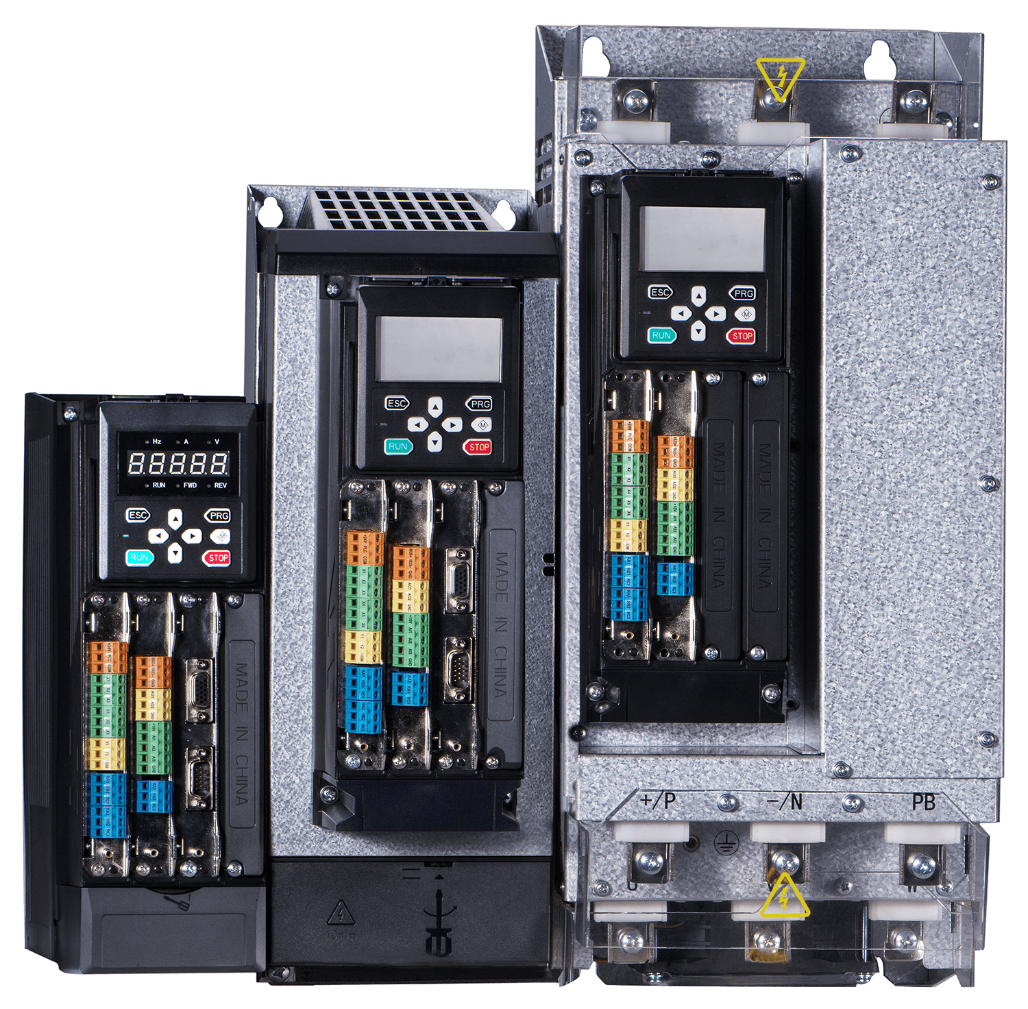
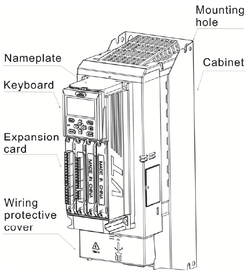
◪Operation panel
Chinese/English liquid crystal display keyboard and LED keyboard, abundant information and convenient debugging;
With multi-functional combination key; for example, realize remote/local switching, emergency shutdown and other humanized functions;
Include parameter storage chip, so that the customer is convenient to storage, upload and download the parameters. It is specifically suitable for batch supporting customers, the debugging time is saved greatly; and the installed efficiency is improved.
Support the scheme of extension cord;
◪Strong motor adaptation ability
Be compatible with synchronous motor, asynchronous motor, reluctance motor, electric main shaft and other motors;
Support the open-loop vector of synchronous motor, open-loop vector of asynchronous motor, closed-loop vector of synchronous motor, open-loop vector control of asynchronous motor, etc.
◪Be compatible with the encoders with multiple specifications
Support the photoelectric encoder, rotary transformer encoder and sine and cosine encoder;
Support accessing the motor encoder and auxiliary encoder into the drive at the same time to realize the double-loop control; when ensuring the stability of the control system, the error of the mechanical drive can be eliminated, so the encoder is specifically suitable for the machine tool, bending machine and other industries. For example, the motor encoder is used as the motor speed control; and the auxiliary encoder is used as the position control.
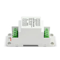
◪Abundant extended function
I/O card can be highly customized according to the demands of the customers;
Support plug and convenient for wiring and maintenance;
I/O terminals with different functions select the design with different colors so as to reduce the probability of error wiring of users greatly; and it is easy to use, beautiful and practical.
◪Book structure, small volume and light weight
Compared with other products of the Company, the volume and weight are reduced by 50%.
The book structure can save the installation space.
◪ Abundant communication interface
Standard Modbus 485 communication, CANopen communication, optional Ether CAT, PROFIBUS-DP, Profinet, MIII, RTEX, POWERLINK and other communications;
Modbus 485 supports 15 groups of user address free mapping, so it is flexible and convenient.
◪ Abundant and perfect protection function
It has abundant and perfect protection functions, such as undervoltage, overvoltage, overcurrent, overheat, overload, peripheral protection, output grounding short circuit, encoder disconnection, motor overload and overheating, etc.
◪ Abundant multi-functional card
Three groups of high-speed chip communication interface
Support extension CPU development
Development of function extension card for industrial machine
Support the secondary application and development of customers to the hardware and software;


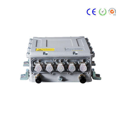
VTS General Purpose Inverter / Servo Drive
Representative Industry
Printing Packaging, Petrochemical, Textile, Cable Machinery, Food Packaging, Electric Vehicles, Plastic Machinery, Metal Products Equipment, Centrifuges and High-end applications requiring closed-loop vector or torque control.
VTS series overview
Because of adopting brand-new vector control technology, VTS series inverter can be compatible with the control of synchronous motor, asynchronous motor and reluctance motor, as well as the encoders with multiple specification and abundant communication interface and support Chinese/English liquid crystal display, five-digit digital pipe display operation panel; and with the protection functions of usability, extendibility, small volume, light weight and perfection, the VTS series inverter can meet the medium-high application demands.
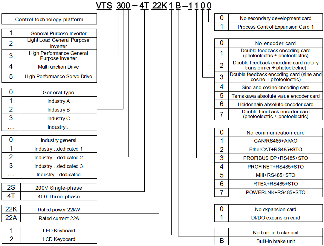
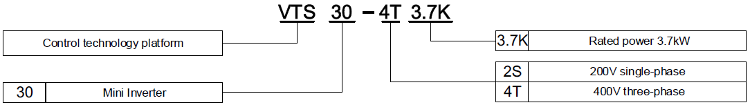
◪VTS□□□−4T□□□K Three−phase 400V Constant torque/heavy application
Power(kW) | 37 | 45 | 55 | 75 | 90 | 110 | 132 | 160 | |
Adapted motor power(kW) | 37 | 45 | 55 | 75 | 90 | 110 | 132 | 160 | |
Output | Voltage (V) | 3-phase 0 -rated input voltage | |||||||
Rated current (A) | 75 | 91 | 112 | 150 | 176 | 210 | 253 | 304 | |
Maximum current (A) | 135 | 164 | 202 | 270 | 317 | 378 | 400 | 547 | |
Overload capability | 150% 1min,180% 10s, 200% 0.5s,10min interval (Inverse-time characteristic) | ||||||||
Input | Rated voltage / frequency | 3-phase 380V-480V;50Hz/60Hz | |||||||
Allowable voltage | 323V-528V;Degree of voltage unbalance:≤3%;Allowable frequency fluctuations:±5% | ||||||||
Rated current (A) | 69 | 89 | 106 | 139 | 164 | 196 | 240 | 287 | |
Brake unit | Built-in brake unit is optional | External brake unit is necessary | |||||||
Protection level | IP20 | ||||||||
Cooling method | Forced cooling | ||||||||
※Note: * 0.75kW - 15kW: no built-in DC reactor
18.5kW-160 kW: standard configured with built-in DC reactor
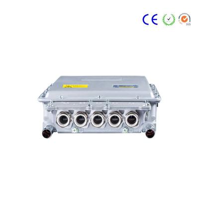
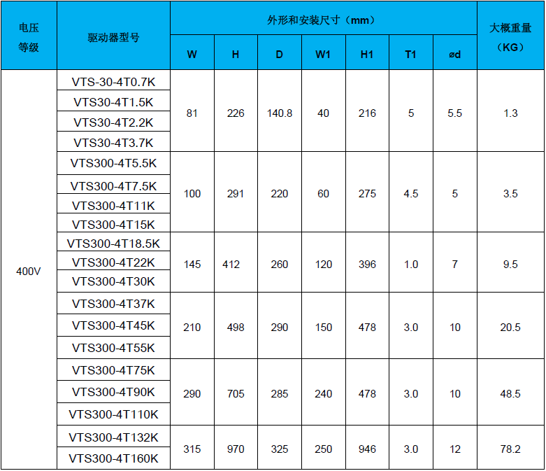
◪Product appearance, installation dimensions, approximate weight
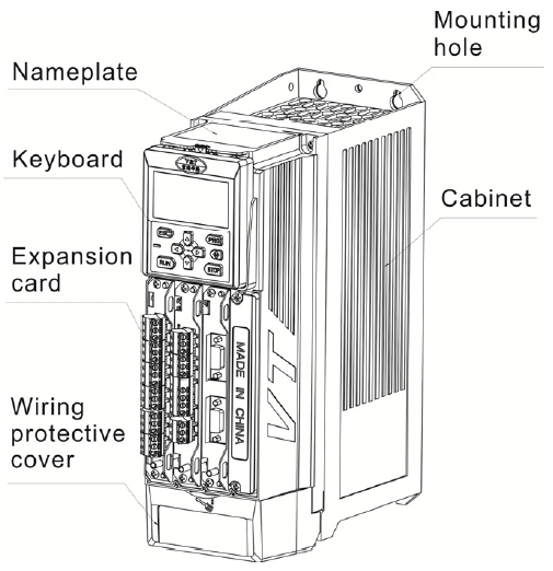
5.5kW-15kW Power Level 18.5kW-160kW Power Level
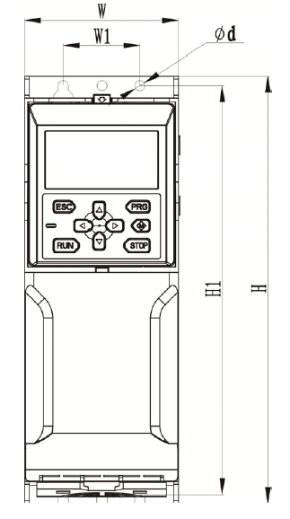
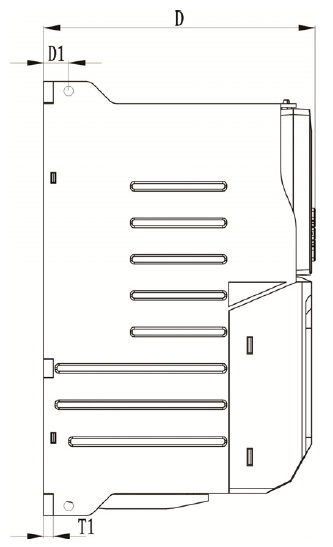
0.7kW-3.7kW Power Level
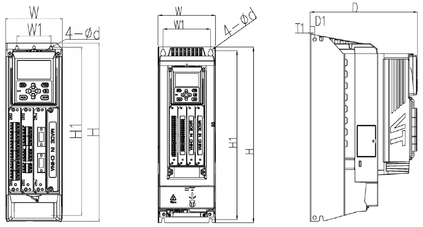
5.5kW -15kW Power Level 18.5kW-160kW Power Level
◪Product appearance, installation dimensions, approximate weight
What are the requirements for cabinet installation of the inverter?
A: The cabinet installation of the inverter is to install the inverter and other electrical equipment used in the inverter in the cabinet. Pay attention to the following two requirements during installation.
(1) When the temperature inside the cabinet is high, an exhaust cooling fan must be installed on the top of the cabinet. The cooling fan should be installed as far as possible directly below the inverter to obtain better cooling effect.
(2) When multiple inverters are installed in the cabinet, the inverters should be installed horizontally as far as possible. If the inverters must be arranged in a vertical manner, a slab should be added between the two inverters, or the upper and lower inverters should be staggered appropriately to avoid The hot air discharged from the inverter goes into the inverter above.
What are the requirements for the installation arrangement of multiple inverters?
Answer: If two or more inverters are installed in the same control cabinet, they should be installed side by side as much as possible. When installing, pay attention to the need to leave a certain gap between the inverters, and pay attention to the ventilation in the control cabinet, so that the temperature around the inverter does not exceed the allowable value. However, if multiple inverters are installed and the space of the control cabinet is small, and only vertical placement can be used, a protective plate should be installed between the upper inverter and the lower inverter to prevent the heat of the lower inverter from causing the temperature of the upper inverter. Rises, causing the inverter to malfunction.
Contact
Supplier