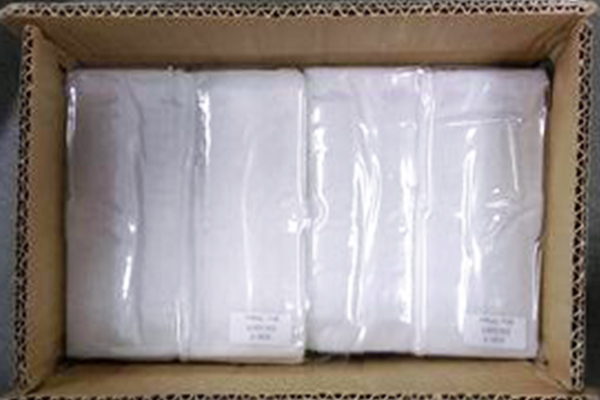
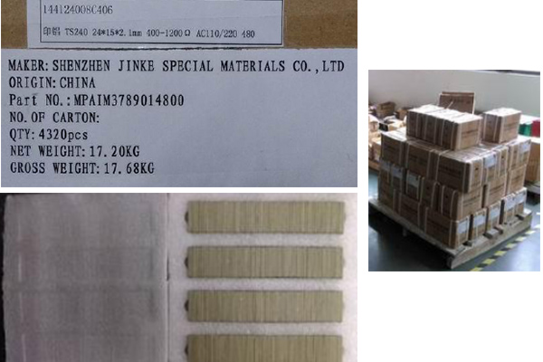
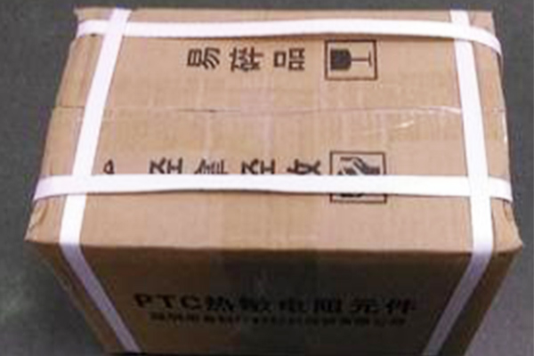
Standard packing: Plastic bag + foam plates + Cartons
++


The Below are our main products. If you have other specifications, please explain. We confirm that we will reply to you for the first time.
| Available Designs | |||||||
| Model No. | Dimension | Ts | Inrush | Voltage | Resistant | Certificate | File No. |
| (mm) | (℃) | (A) | (V) | (Ω) | |||
JK080F3A1B | 24*15*2.5 | 115 | ≤3 | 100-240 | 200-2000 | UL/CUL | E217453 |
JK135F2C4B | 25*9*2.1 | 170 | ≤3 | ||||
JK185F3A1B | 24*15*2.5 | 215 | ≤3 | ||||
JK215F3B6B | 35*6*2.5 | 240 | ≤3 | ||||
JK235F2D2B | 23*13*2.1 | 260 | ≤4 | ||||
JK120F6A8A | 24*10*2.0 | 130 | ≤4 | ||||
JK140F2A2A | 24*13*2.1 | 160 | ≤4 | ||||
JK185F6A8A | 24*10*2.0 | 200 | ≤4 | ||||
JK190F3A1A | 24*15*2.5 | 200 | ≤4 | ||||
JK190F2A2A | 24*13*2.1 | 200 | ≤4 | ||||
JK220F3A1A | 24*15*2.5 | 235 | ≤4 | ||||
JK225F6A8A | 24*10*2.0 | 240 | ≤4 | ||||
JK240F2A5A | 24*8*2.1 | 250 | ≤4 | ||||
JK240F3A8A | 24*10*2.5 | 250 | ≤4 | ||||
JK240F2A1A | 24*15*2.1 | 250 | ≤4 | ||||
JK250F6A8A | 24*10*2.0 | 270 | ≤4 | ||||
JK210F3B2A | 35*13*2.5 | 220 | ≤4 | ||||
JK180F3B2A | 35*13*2.5 | 190 | ≤4 | ||||
JK245F3A1B | 24*15*2.5 | 270 | ≤4 | ||||
JK245F8B2A | 35*13*2.3 | 270 | ≤4 | ||||
JK180F8B2A | 35*13*2.3 | 190 | ≤4 | ||||
JK240F6B2A | 35*13*2.0 | 260 | ≤4 | ||||
JK210F6B2A | 35*13*2.0 | 230 | ≤4 | ||||
JK190F6B2A | 35*13*2.0 | 200 | ≤4 | ||||
JK150F6B2A | 35*13*2.0 | 170 | ≤4 | ||||
JK245F8B8A | 35*10*2.3 | 270 | ≤4 | ||||
JK245F3B9A | 35*10*2.5 | 270 | ≤4 | ||||
JK190F2J8A | 33*10*2.1 | 200 | ≤4 | ||||
JK245F8K2A | 30*13*2.3 | 270 | ≤4 | ||||
JK225F8K2A | 30*13*2.3 | 245 | ≤4 | 110-240 | 200-2000 | UL | E217453 |
JK245F3B5A | 35*8*2.5 | 270 | ≤4 | ||||
JK210F5B6A | 35*6*2.7 | 220 | ≤4 | ||||
JK180F5B6A | 35*6*2.7 | 190 | ≤4 | ||||
JK150F5B6A | 35*6*2.7 | 160 | ≤4 | ||||
JK245F3B6A | 35*6*2.5 | 270 | ≤4 | ||||
JK245F8B7A | 35*6*2.3 | 270 | ≤4 | ||||
JK180F8B6A | 35*6*2.3 | 190 | ≤4 | ||||
JK240F6B6A | 35*6*2.0 | 260 | ≤4 | ||||
JK210F6B6A | 35*6*2.0 | 230 | ≤4 | ||||
JK190F6B6A | 35*6*2.0 | 200 | ≤4 | ||||
JK150F6B6A | 35*6*2.0 | 170 | ≤4 | ||||
JK245F3A2A | 24*13*2.5 | 270 | ≤4 | ||||
JK245F8A2A | 24*13*2.3 | 270 | ≤4 | ||||
JK245F3A8A | 24*10*2.5 | 270 | ≤4 | ||||
JK245F6A0A | 24*4*2.0 | 260 | ≤4 | ||||
JK170Y43A | ø12*2.5 | 190 | ≤4 | ||||
JK120Y43A | ø12*2.5 | 140 | ≤4 | ||||
JK190Y53A | ø8.5*2.5 | 210 | ≤4 | ||||
JK150Y53A | ø8.5*2.5 | 170 | ≤4 | ||||
JK110Y53A | ø8.5*2.5 | 130 | ≤4 | ||||
JK150F9I7A | 5*4*1.6 | 160 | ≤4 | 400-2000 | |||
JK170F6B6A | 35*6*2.0 | 180±15% | 12 | 220-240 | 200-2000 | TUV | R50053836 |
JK200F6A8A | 24*10*2.0 | 210±10% | 12 | ||||
JK215F6B6A | 35*6*2.0 | 225±10% | 12 | ||||
•Rated Voltage: 6V~48V 100~120V 200~240V
•Curie Temperature: 50~280 °C
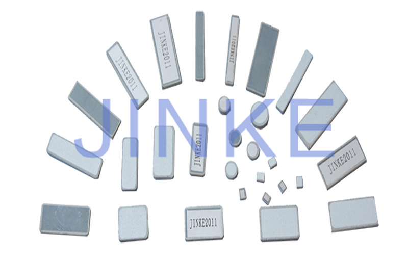
•Resistance Range: 0.4~5.0K ohm
•Dimension: 5x 4mm~ 35x20 mm
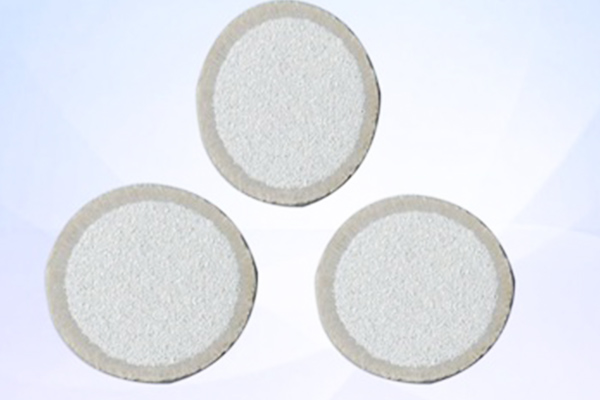
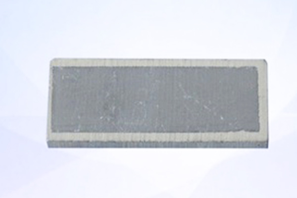
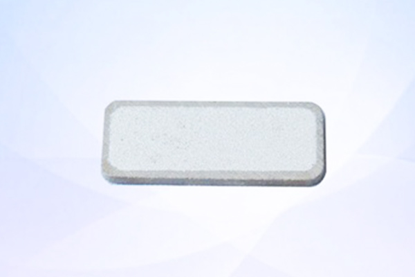
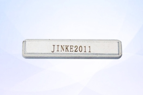
•Types: Circle , rectangle , ring
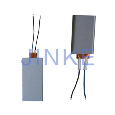
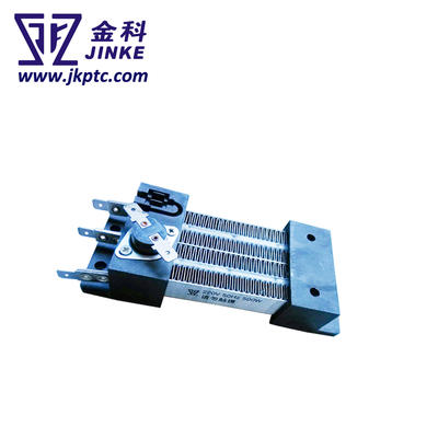
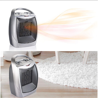
•Fan heating element for ceramic heater fan, hair dryer, hand dryer, clothes dryer, dish dryer etc.
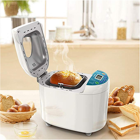
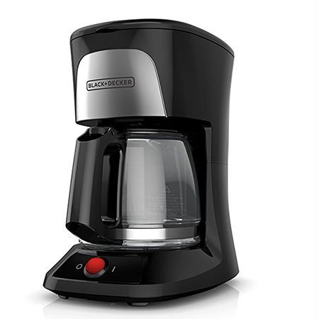
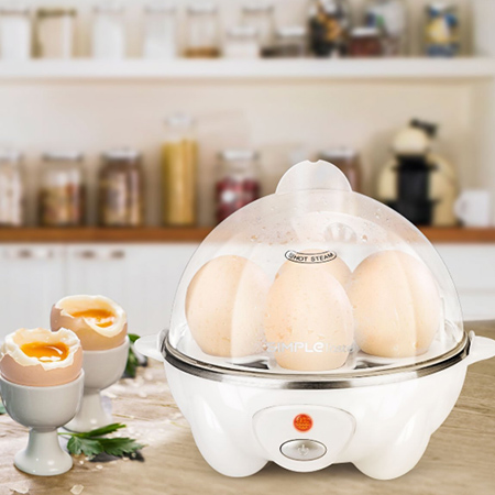
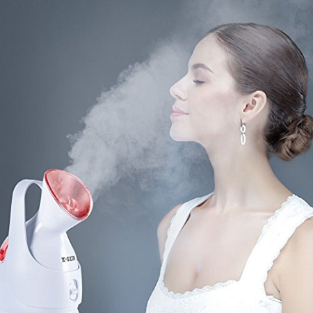
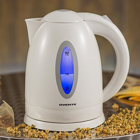
•Heating plates for coffee makers, steam irons, cooking devices, facial sauna, humidifier etc.
•Tube heating elements for curing irons, wax-warmer, glue gun, dehumidifier etc.
•Other shapes of heating element can be used for mosquito repellent, liquid warmer, control devices etc.


❈ Faq

What is your minimum order quantity?
At least 1000pcs for each item.
What is the delivery period?
About 20-25days, it is up to your order quantity.
What is your payment term?
T/T(30% before production and 70% before shipment),L/C,D/A, D/P, T/T, Western Union, MoneyGram, OA
Can you send free samples?
We can send free samples.
What is your shipping ways?
For sample we usually send by DHL, FEDEX, UPS, THT, EMS(taking 5-7business days). For mass product we are shipping by sea or by air.
PTC selection method and steps Step 1: Determine the circuit parameters You need to determine the following parameters of the circuit: Maximum working environment temperature Standard working current Maximum working voltage Maximum interrupting current PTC devices use a reduction ratio [ambient temperature (° C) holding current (A)] table and select the temperature that best matches the maximum ambient temperature of the circuit. Browse this column to see values that are equal to or greater than the standard operating current of the circuit. Now look at the far left of the row to see the device family best suited for this circuit. Step 3: Compare the maximum electrical rating of the selected device to the maximum operating voltage and interrupt current of the circuit.Use the electrical characteristics table to verify that the part you selected in step 2 will use the maximum operating voltage and interrupt current of the circuit. . Check the device's maximum operating voltage (Vmax) and maximum interruption current (Imax). Ensure that Vmax and Imax are greater than or equal to the maximum operating voltage and maximum interrupt current of the circuit. Step 4: Determine the action time. The action time is the amount of time it takes to switch the device to a high resistance state when a fault current passes through the device. In order to provide the desired protection function, it is important to know the operating time of the PTC device. If the device you select moves too fast, it may cause abnormal or erroneous operation. If the device moves too slowly, the protected device may be damaged before the device moves and limits the current. Use the typical operating time curve at 25 ° C to determine whether the operating time characteristics of the PTC device can be accepted under the expected fault current. If not, go back to step 2 and choose another alternative device. Step 5: Verify the ambient operating temperature Ensure that the minimum and maximum ambient temperatures for the application are within the operating temperature range of the PTC device. Most PTC devices have an operating temperature range of -40 ° C to 85 ° C, and in some special cases can reach 125 ° C. Step 6: Verify the external dimensions of the PTC device Use the external dimensions table to compare the external dimensions of the PTC device you selected with the space conditions of the application. Parameter definition description: IH Maximum working current at 25 ℃ ambient temperature IT Minimum current Vmax for PTC device protection at 25 ℃ ambient temperature The maximum working voltage of PTC device safe disconnection, also known as Maximum Device Voltage, Maximum Voltage, Vmax , Max Interrupt Voltage Imax The maximum fault current at which the PTC device can safely operate at 25 ℃ ambient temperature Rmax The initial maximum resistance before the PTC device is not activated at 25 ℃ ambient temperature Rmin value
Contact
Supplier
Agriculture Machinery & Equipment
Apparel & Textile Machinery
Building Material Machinery
Chemical Machinery & Equipment
Energy & Mineral Equipment
Engineering & Construction Machinery
Food & Beverage Machinery
Home Product Making Machinery
Industry Laser Equipment
Machine Tool Equipment
Metal & Metallurgy Machinery
Other Machinery & Industry Equipment
Packaging Machine
Paper Production Machinery
Plastic & Rubber Machinery
Printing Machine
Woodworking Machinery
Environmental Machinery
Machinery Accessories
Material Handling Equipment
Welding Equipment
Cleaning Equipments
Commercial Machinery
Air-Compressors & Parts